ASRock Motherboard Utility — что это за драйвер?
 Не драйвер, а программа со многими полезными функциями, например разгон процессора, оптимизация ОЗУ, настройка вентиляторов, ускорение загрузки Windows и многое другое.
Рекомендована к установке.
Под названием ASRock Motherboard Utility скрывается ПО — ASRock A-Tuning Utility, которое из себя представляет пакет основных компонентов (которые раньше поставлялись отдельно):
- XFast RAM — для оптимизации работы оперативной памяти. Программа способна создавать виртуальные диски из оперативки для временных файлов. При использовании 32-битных операционок — программа может задействовать память, которую Windows не видит (если у вас больше 4 гб ОЗУ).
- XFast LAN — для расстановки сетевых приоритетов. Например вы играете в онлайн игру, кроме этого у вас открыты другие программы, которые могут использовать интернет. При помощи XFast LAN можно выставить высокий приоритет процессу онлайн игры, в которую вы играете, так как это важнее всего. А остальное ПО, например Скайп, Вайбер, браузеры — могут подождать. В итоге в игре у вас задержки могут стать намного ниже, другими словами — пинг меньше.
- Dehumidifier — функция для защиты материнской платы от конденсата. При включении — ПК автоматически начнет осушение системы после перехода в режим S4/S5.
- FAN-Tastic Tuning — управление вентиляторами. Скорее всего также присутствует автоматический режим, при котором скорость зависит от температуры.
- Fast Boot — ускорение Windows. На самом деле ускорение происходит за счет отложенного запуска программ из автозагрузки.
- USB Key — защищенный вход в учетную запись.
- Good Night LED — функция, которая отключает все светодиоды. Как понимаю присутствует на платах с подсветкой (например она может быть под чипсетом).
Это только некоторые компоненты. Их может быть больше, зависит от версии ПО.
Внешний вид утилиты ASRock A-Tuning Utility:
 Сразу видим — утилита в том числе позволяет перевести ПК в режим повышенной производительности (Perfomance Mode — возможно это некий разгон), обычный режим (Standart Mode), тихий и энергосберегающий режим (Power Saving).
Также в утилите есть компонент обновления фирменного софта ASRock:


Настройка работы вентиляторов:

Как я и думал, при помощи данной утилиты можно разгонять процессор:

Как удалить программу? Возможно она вам окажется ненужной, поэтому вот простой способ как ее удалить:
- Зажимаете Win + R, появится окошко Выполнить — вставляем команду appwiz.cpl, нажимаете ОК.
- Появится окно со списком установленного ПО.
- Находим ПО ASRock Motherboard Utility, нажимаем правой кнопкой и выбираем Удалить.
- Далее запустится модуль удаления (деинсталляции) или программа сразу удалится без окошек.
На этом все, надеюсь информация оказалась полезной. Удачи и добра, до новых встреч друзья!
Обзор материнской платы Asrock Z590m Pro4

Совсем недавно (а именно в конце 1 квартала 2021 года) в продаже появилось новое (11-е) поколение процессоров от компании Intel и одновременно производители представили материнские платы на чипсетах 500-й серии.
В этом обзоре речь пойдет об одной из самых бюджетных плат на чипсете Z590 — Asrock Z590m PRO4 в форм-факторе micro-ATX.
Упаковка и комплектация
Упаковка у платы стандартная без особых изысков. В комплект поставки кроме самой платы входит:
- задняя планка
- 2 кабеля сата (прямой и угловой)
- набор винтиков для крепления плат m.2
- мануал и диск с драйверами
- фирменная наклейка!

Технические характеристики
Для начала приведу список основных характеристик, затем рассмотрим отличия от других чипсетов.
Более полный список характеристик можно найти на сайте производителя или в карточке товара на сайте ДНС.
Теперь несколько слов от чипсете Z590. От предыдущего топового чипсета Z490 он почти не отличается. Основные отличия между поколениями — в процессорах. В частности, в новом поколении процессоров поддерживается 24 процессорные линии PCIe вместо 20, что позволяет подключить напрямую к процессору не только видеокарту, но и NVME-накопитель (ранее они подключались к чипсету).
Новый чипсет соединяется с процессором по 8 линиям DMI вместо 4-х, что позволяет удвоить пропускную способность. Это может быть полезно при подключении быстрых SSD-накопителей или RAID-массивов к чипсету.
Процессоры и чипсеты теперь поддерживают вдвое более быструю версию PCI-E – 4.0. Впрочем, производители топовых материнских плат 400-й серии пообещали поддержку PCI-E 4.0 и там. Так что это отличие не принципиальное.
Также увеличена максимальная скорость портов USB 3.2 до 20 Гбит/сек, что мало кому нужно. Кроме того, на этой плате порты USB 3.2 имеют максимальную скорость все также 10 Гбит/сек (по крайней мере, если верить спецификации).
Основное отличие чипсета Z590 от других представителей линейки, а именно H570, B560, H510 — в наличии возможности разгона процессоров с индексом «К». Разгон памяти теперь поддерживают чипсеты H570 и B560, так что, если вы планируете ограничиться разгоном памяти, можно взять модель попроще.
Также у других чипсетов меньше процессорных и чипсетных линий PCI-E, линий DMI и USB-портов.
Внешний вид и описание отдельных опций
Давайте посмотрим на плату чуть внимательнее.

На плате установлено 4 разъема для установки памяти типа DDR4. Максимальный объем памяти — 128 Гигабайт. Официально поддерживается разгон памяти до 4800 МГц с процессорами 11 поколения и до 4666 МГц с процессорами 10 поколения.
Я подозреваю, что на частотах выше 3,6 — 4,0 ГГц контроллер памяти придется запускать на половине частоты памяти (Gear2), так что пользы от таких высоких частот будет не много.
Производитель оснастил плату 12-фазной системой питания процессора и довольно массивными радиаторами (выглядят они максимально просто и дешево). Разъем питания процессора имеет 8+4 пин.
Чтобы понять, как устроена система питания нужно снять с неё радиаторы. Откручиваем 4 болта и снимаем 2 радиатора с довольно узкими основаниями. С транзисторными сборками он контактируют через толстые термопрокладки (примерно 2 мм толщиной).

Системой питания управляет ШИМ-контроллер RT3609BE от компании Richtek. Он может управлять 8-ю фазами питания: 6 фаз — на питание ядра процессора, 2 фазы — на питание графического ядра. Ниже приведена схема питания из даташита.

Шим-контроллер работает с частотой 400 кГц, точность напряжения на выходе ±0,5%.
На левом фото ниже видны 6 DrMOS-ов (сокращение от Driver + MOSFET) SIC654A. Эти транзисторные сборки отвечают за питание ядра процессора и видеоядра и могут пропускать через себя ток в 50А на постоянной основе (до 70А в пике). Второй ряд из 7-и DrMOS-ов расположен под вторым радиатором.
Итого имеем 13 DrMOS-ов, что не совсем совпадает с даташитом ШИМ-контроллера. Точной информации по схеме питания я не нашел. Предполагаю, что 10 DrMOS-ов управляются 5-ю фазами и питают ядро, т.е. на каждую фазу приходится 2 канала с максимальным током в 100А. Общий ток питания ядра, таким образом, составляет максимум 500А или примерно 550Вт. Вполне неплохой запас мощности, даже в какой-то степени избыточный.
Ещё 2 DrMOS`а – это 2 фазы питания видеоядра. Видеоядро у i7-11700, к примеру, потребляет 15Вт мощности, так что здесь тоже мощности с избытком.
Ну и один DrMOS – это питание кольцевой шины. Он управляется ШИМ-контроллером RAA229001.
На левом фото также видны два полевых транзистора (PQ16 и PQ17) с маркировкой 4508NH, которые отвечают за питание контроллера памяти (максимальный постоянный ток 48А).
На плате есть 4 разъема PCI-express. Разъем PCI-E x16 имеет металлическое армирование и подключается напрямую к процессору. С процессорами 11-го поколения разъем может работать в режиме PCIe 4,0, а с 10-м поколением только PCIe 3.0.

Также есть 2 разъема PCIe x1 и один PCIe x4. Да, он выглядит как полноценный разъем х16, но половины линий у него просто нет, что хорошо видно по отсутствующим контактам в разъеме. Все разъемы, кроме первого, поддерживают только стандарт PCIe 3.0 и подключаются к чипсету.
Далее перейдем к разъемам m.2 на плате. Один разъем предназначен для подключения адаптера WiFi и BT, в два других разъема можно подключить SSD.
Ближний к процессору разъем имеет фирменный радиатор, подключается напрямую к процессору по 4 линиям PCIе и в зависимости от поколения процессора может работать в режиме PCIe 3.0 или 4.0. Также поддерживается работа в режиме SATA3 со скоростью до 6 Гбит/с.
Разъем m.2 около чипсета подключается к чипсету и работает в режиме PCIe 3.0 или SATA3.
Плата поддерживает объединение накопителей в Рейд-массивы:
- RAID 0, RAID 1, RAID 5 и RAID 10 для накопителей SATA
- RAID 0 и RAID 1 для накопителей m.2 NVMe

На задней панели набор разъемов спартанский:
- 2 порта USB 2.0 плюс разъем PS/2
- выдеовыходы HDMI 1.4 и DisplayPort
- 4 порта USB 3.0 (Gen1 и Gen2)
- разъем LAN, поддерживающий скорость до 1 Гбит/с
- блок аудио-разъемов
За звук отвечает чип Realtek ALC897, весьма средний по качеству звука, насколько я понял. За сетевой интерфейс отвечает чип Intel i219v.
Далее быстренько пройдемся по остальным разъемам.
На плате распаяно 4 порта SATA3, причем, если ближайший к процессору разъем m.2 будет занят SATA-накопителем, то один из 4-х портов не будет работать.
Есть 4 разъема для подключения светодиодных лент. Из них два обычных 12-вольтовых с 4-я пинами (держат ток до 3 А), а два — с адресацией, 3-пиновые. На них напряжение 5В, ток также до 3А.

На плате есть 2 разъема для подключения внешних портов USB 3.0, а также один разъем для подключения USB 3.2 type-c. На современных корпусах, кстати, они пока встречаются не часто.

На плате достаточно много разъемов для подключения вентиляторов. Для охлаждения процессора можно задействовать 2 разъема, в том числе один рассчитан на подключение помпы. Для подключения корпусных вентиляторов или СЖО можно задействовать аж 4 разъема.
Отдельно отмечу наличие разъема для подключения модуля шифрования, так называемого TPM, который может, к примеру, на лету шифровать данные на накопителях.
Также присутствует UART или проще говоря COM-порт.
Установка платы и настройка BIOS
Плата устанавливается на 8 опор, левый нижний угол на фото слегка провисает.

Если планируете использовать wifi-адаптер для разъема m.2, на задней планке есть 3 отверстия для установки антенн.

Далее вкратце пройдемся по настройкам БИОС. Вначале нас встречает упрощенный интерфейс, на котором можно выбрать только несколько настроек.

При нажатии F6 отображаются уже все настройки. Наиболее интересен раздел «OC Tweaker», где можно разгонять процессор и память. Пункт «Base Frequency Boost» позволяет установить предел мощности для процессора в пределах от 70 до 230 Вт, что просто приведет к изменению соответствующих настроек в разделе «CPU Configuration», так что лучше сразу настраивать потребление процессора там.

В разделе «CPU Configuration» наиболее важные настройки следующие:
Short Duration Power Limit – повышенный лимит мощности при кратковременной нагрузке
Long Duration Maintained – время кратковременной нагрузки
Long Duration Power Limit – лимит мощности при постоянно нагрузке
Такое разделение на режимы повышенной и «нормальной» мощности необходимы исключительно для процессоров с боксовыми кулерами и возможности указать в их спецификациях «TDP 65Вт».
Если у вас нормальный кулер — можно поднять лимиты до 105Вт для i5-11400F и до 130 Вт для i7-11700. В итоге процессор будет работать с максимально возможной производительностью.
Раздел «DRAM configuration» позволяет выбрать и загрузить данные из XMP-профиля планок. Материнская плата распознала оба имеющихся профиля. В пункте «Load XMP settings» вы можете выбрать режим «Авто» или указать конкретный профиль. Явно отказаться от загрузки профиля нельзя. Вместо этого можно загрузить профиль, а затем вручную выставить нужные тайминги. Реализация весьма странная как по мне.
После установки длинного списка таймингов можно выбрать дополнительные опции типа автоматической оптимизации таймингов (суть которой нигде не объясняется) или возможности изменения таймингов в реальном времени.
Следующий раздел «Voltage Configuration» позволяет выставить нужные напряжения.

Здесь есть один маленький, но очень большой нюанс. Система не отображает значение «VccSA Voltage», а просто позволяет выбрать режим «Авто», «Offset» (смещение) и «Fixed» (фиксированное напряжение).
В режиме «Авто» напряжение VccSA составляет 1,5В (!). Версия биос при этом последняя — P1.6. Это можно увидеть при помощи утилит типа HWInfo. Такой уровень напряжения является очень высоким. Я установил значение 1,3В в режиме «Fixed» и все отлично работает. Написал вопрос в техподдержку Asrock, посмотрим что ответят.
На других вкладках присутствуют более-менее обычные настройки, которые нет смысла описывать. Разве что настройка RGB-подсветки платы выполняется на вкладке «Tool».
Температура ВРМ и чипсета
На плате есть датчик, но не совсем понятно, в каком месте он измеряет температуру. При потребляемой процессором мощности в 126Вт и температуре 66 градусов, это датчик показывал только 35 градусов на плате.

Температуры радиаторов ВРМ, измеренные электронным термометром, в это же время были: большой радиатор — 41ºС, малый радиатор — 42ºС. Это немного выше показаний бесполезного датчика, но все равно, нагрев невысокий.
Температура радиатора чипсета оказалась заметно выше: от 51 до 55 градусов. Причем наличие нагрузки (например тестирование SSD) на температуру никак не влияло. Чипсет просто отлично обогревал пространство системника 100% времени.
Кусок алюминия с надписью ASRock тут явно не слишком уместен. Чипсет требует радиатора с большим количеством ребер и более-менее хорошего обдува. Хотя, температура в 55 градусов для современных микросхем считается нормальной.
Программное обеспечение
Не все драйверы для материнской платы Windows 10 может установить сама. Чтобы из диспетчера устройств пропали вопросительные знаки, на сайте Asrock вам придется скачать и установить как минимум следующие драйверы:
- Драйвер INF
- Intel Драйвер LAN
- Драйвер Intel Management Engine
Весь список доступного ПО выглядит следующим образом

Вкратце пройдусь по нескольким позициям.
Драйвер аудио Realtek и Nahimic Utility
Драйвер аудиокарты просто заменяет собой драйвер, который Windows устанавливает по-умолчанию. Из изменений — только изменение имени аудиоустройства.
Программа Nahimic – програмный улучшайзер звука. Добавляет эффекты 3D и все в таком духе. После установки ПО оказывается, что его нужно установить через MS store, который у меня не хочет работать. Так что, увы, моё знакомство с этим куском кода не состоялось.

A-Tuning (Asrock Motherboard Utility)
Это программа для тонкой настройки параметров материнской платы. Здесь можно установить множитель (для «K»-процессоров), настроить напряжения и скорости работы вентиляторов.
Asrock PolyChrome RGB
Это утилита для управления подсветкой. Отдельно можно выбирать каждый элемент, поддерживающий изменение подсветки (у меня это планки DDR4 и сама плата).

Утилита кривая и глючная, как и многие подобные утилиты от других производителей. Выбор подсветки платы то блокируется, то опять становится доступным. Одноцветная подсветка на разных элементах смотрится нормально, а вот смена цветов не синхронизируется. В общем, на любителя.
Утилита Intel Rapid Storage
Используется вместе с памятью Optane для ускорения работы системы. Ранее данная утилита позволяла использовать кэширующий SSD для ускорения работы жесткого диска. Насколько я знаю, в последних версиях они оставили только поддержку Optane.
В любом случае, после установки драйвера требуется установка самой утилиты из MS Store. Так что и этот кусок кода остался без внимания.
Выводы
Asrock Z590m Pro4 – бюджетная плата для небольших корпусов с одной из самых низких цен.
Из плюсов отмечу неплохую систему питания (правда там всего 8 фаз, а не 12) с хорошим запасом мощности, достаточное охлаждение ВРМ, достаточное количество разъемов, в том числе для подсветки.
Жирный минус — неочевидная проблема с высоким напряжением VccSA=1,5В. По крайней мере на БИОС версии P1.6. Также горячий чипсет очень нуждается в хорошем радиаторе и обдуве корпусными вентиляторами.
ASRock
We use cookies to offer you a more personalized and smoother experience. By visiting this website, you agree to our use of cookies. If you prefer not to accept cookies or require more information, please visit our Privacy Policy.
If you are fully aware of the category of your question, you may choose one of the categories below for frequently asked questions.
Results:
Answer:
Please follow the steps below to disable the iGPU.
This problem happens when using an AM4 motherboard and APU (CPU with integrated graphics), if you also have an AMD discrete graphics card and the Compatibility Support Module (CSM) is disabled in BIOS.
1. Go to BIOS\Advanced\AMD CBS\NBIO Common Options\GFX Configuration and set iGPU Configuration to «Disabled”. 
2. Press hotkey «F10” to save settings and exit the BIOS setup.
3. Boot into the OS and check if the «Record & Stream» menu appears in the AMD Radeon software.

Answer:
Please check below table and follow the instructions.
Overview
| A770 PGD | A750 CLD | A380 CLI | A770 LE | |
| Intel graphics card driver | Required | Required | Required | Required |
| Update the graphics card FW | Required | Required | No need | No need |
| Set PCIe power to «Maximum power savings” | Required | Required | Required | Required |
| Reinstall the graphics card driver and check the «GPU Core Power” | Required | Required | No need | No need |
ASRock ARC graphics card FW update
Procedures
●Intel Graphics Card Driver
Go to Intel’s official website to download and install the latest official graphics card driver. 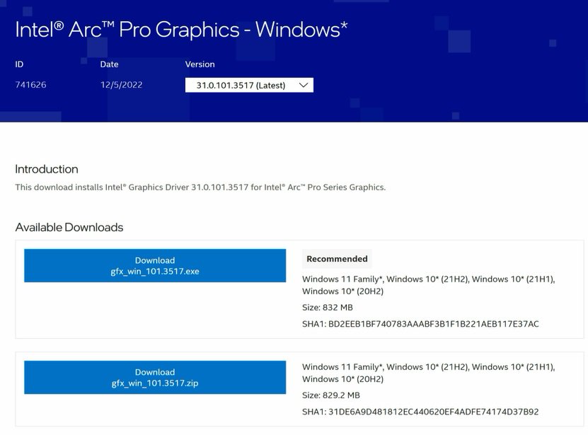
● Update the Graphics Card FW
Step 1. Download and unzip IGFXUpdate(v1.01.1).
Step 2. Run «IGFXUpdate” 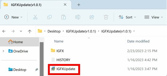
Step 3. Click Yes to restart the system. 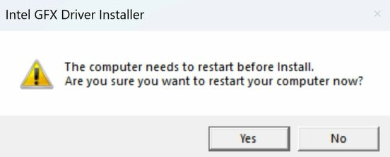
Step 4. After the system has restarted, the FW update will begin.
* If this message doesn’t show up, please disable the «Secure Boot” in BIOS and try again. 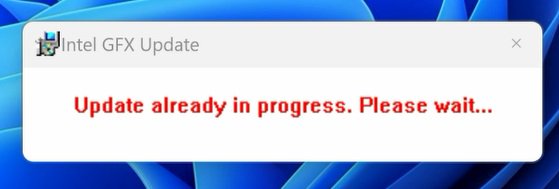
Step 5. During the update, the following security message will pop up. 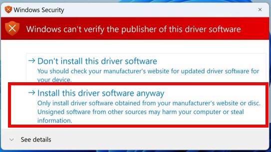
Step 6. Click on Install this driver software anyway.
Step 7. The update process will proceed. The screen might blink during the update.
Step 8. Please restart your computer when the following prompt is shown. 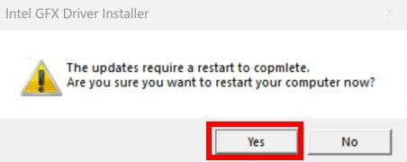
● Set PCIe Power to Maximum Power Savings
Step 1. Go to [Control Panel\Hardware and Sound\Power Options\Edit Plan Settings\Change] and click [Change advanced power settings]. 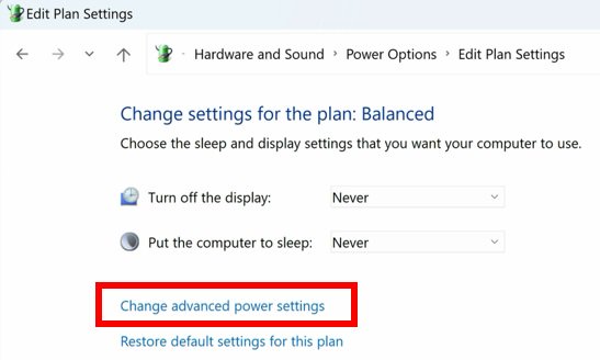
Step 2. Scroll down to PCI Express\Link State Power Management and select Maximum power savings. Make sure to click apply to apply the changes. 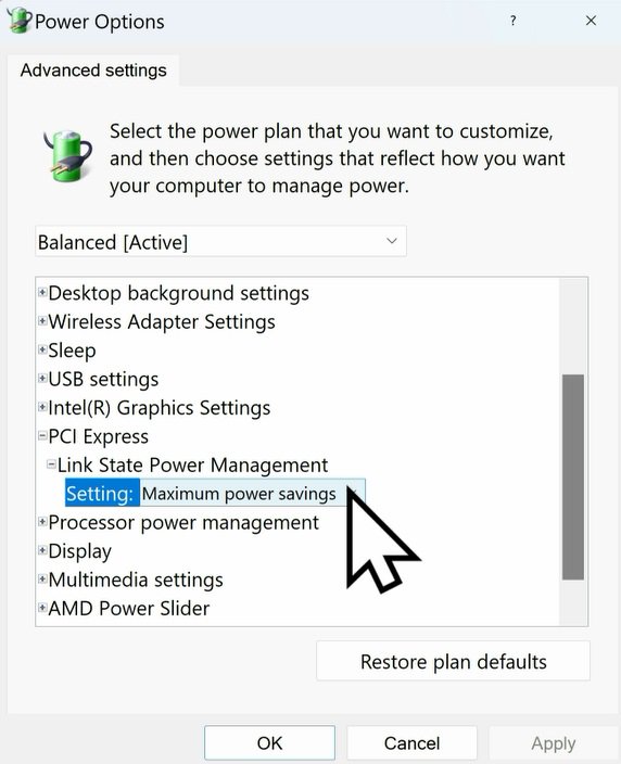
● Re-install the Graphics Card Driver and Check the GPU Power
Step 1. Reinstall the latest graphics card driver.
Step 2. To check the power consumption of the Intel ARC graphics card, please open Intel Arc Control and find the GPU Core Power. 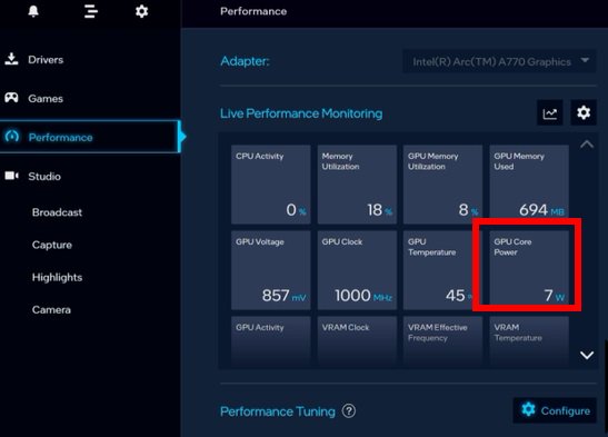
BIOS Setting For ARC GPU Power Saving
● ASRock Intel Motherboard:
Required BIOS Version:
700-series motherboard: Please use the latest BIOS
600/500/400-series motherboard: Use the latest BIOS. It that does not work, please contact ASRock Technical Support. https://event.asrock.com/tsd.asp
BIOS Settings for all ASRock Intel models:
In BIOS > Advanced > Chipset Configuration, apply the following settings.
PCI Express Native Control: Enabled
PCIE ASPM Support: L1
PCH PCIE ASPM Support: L1 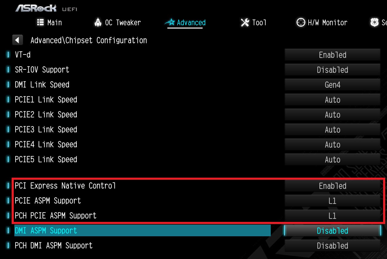
● ASRock AMD Motherboard:
Required BIOS Version:
| Platform | 600 series | 500 series | 400 series | 300 series |
| BIOS version | Any version | Not supported | ||
BIOS Setting for all AMD models:
There is no need to change BIOS settings.
● Other brands motherboard:
Please contact your motherboard vendor for further assistance.
Power Consumption After Updating FW and Changing the BIOS Settings
Answer:
Please flash the RGB controller firmware of the graphics card via the following procedure.
Step 1. Find and download the correct firmware for your graphics card.
| GPU | Model | Download | |
| AMD | RX 7900 XTX | RX7900XTX AQ 24GO | Link |
| RX7900XTX TC 24GO | Link | ||
| RX7900XTX PG 24GO | Link | ||
| RX 7900 XT | RX7900XT TC 20GO | Link | |
| RX7900XT PG 20GO | Link | ||
| RX 6950 XT | RX6950XT OCF 16G | Link | |
| RX6950XT PG 16GO | TBA | ||
| RX 6900 XT | RX6900XT OCF 16G | Link | |
| RX6900XT PGD 16GO | Link | ||
| RX 6800 XT | RX6800XT TCX 16GO | Link | |
| RX6800XT PG 16GO | Link | ||
| RX6800XT PGD 16GO | Link | ||
| RX 6800 | RX6800 PGD 16GO | Link | |
| RX6800 CLP 16GO | Link | ||
| RX 6750 XT | RX6750XT PGD 12GO | Link | |
| RX 6700 XT | RX6700XT PGD 12GO | Link | |
| RX 6650 XT | RX6650XT PGD 8GO | Link | |
| RX 6600 XT | RX6600XT PGD 8GO | Link | |
| Intel | Arc™ A770 | A770 PGD 8GO | Link |
Below steps use the RX 7900 XTX Phantom Gaming 24GB OC (RX7900XTX PG 24GO) as example. File and folder names can be different when using another card.
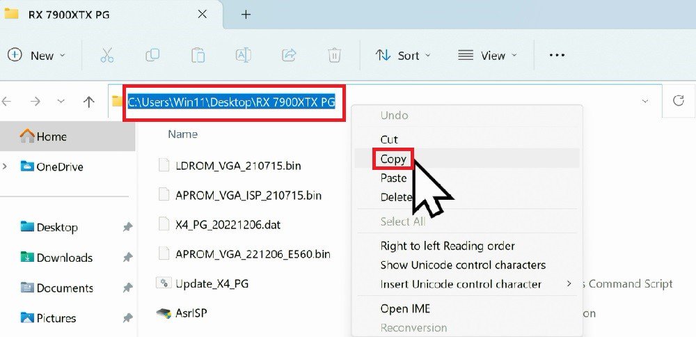
Step 2. Please extract the RGB firmware tool and copy the path of the folder that contains the RGB firmware.
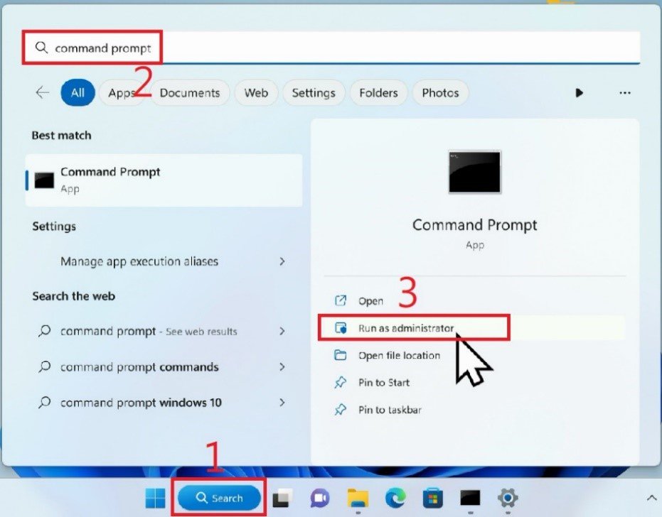
Step 3. Open Command Prompt as administrator.
Step 4. Type cd and paste the path that you have just copied.
Step 5. Hit the Enter key.
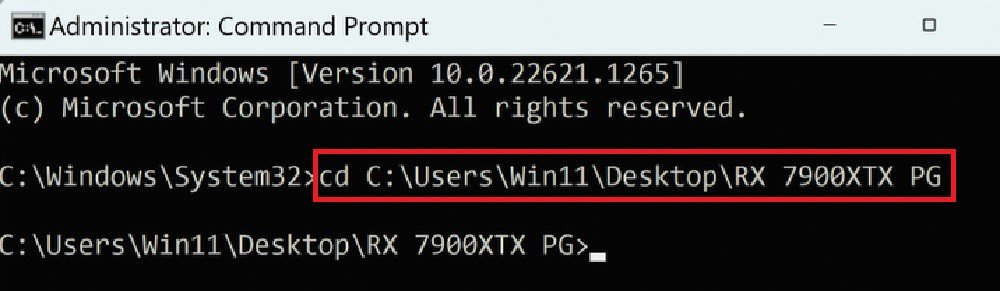
Step 6. Type the word «Update” and press the Tab key on the keyboard. A full command file name will show up.
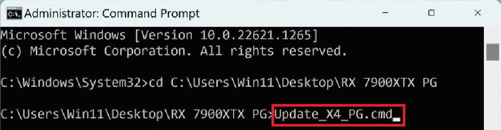
Step 7. Use the Enter key to start flashing the RGB firmware. Give it some time.
Step 8. Once the RGB firmware is updated, the command prompt will show «Update Pass.”
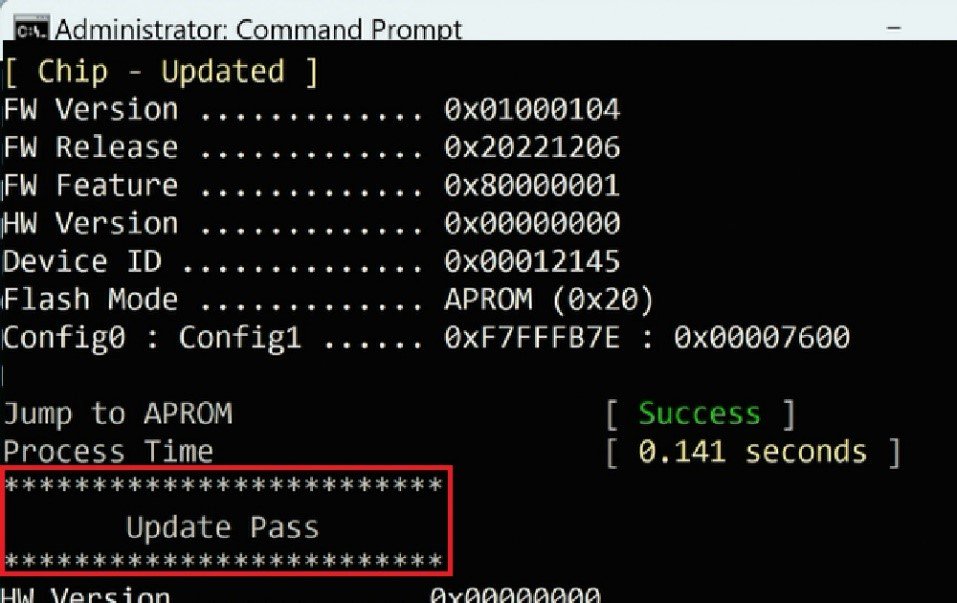
Step 9. Start the ASRock RGB software and check if the graphics card’s RGB lighting can be controlled.
If the latest driver does not fix the problem, please follow below steps to adjust settings manually.
1. Right-click the «Windows Start icon” and choose the [Device manager]. 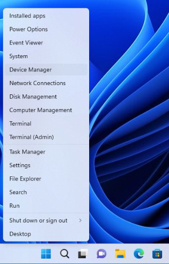
2. Find the «Network adapters”, right-click the [Killer E3100G 2.5 Gigabit Ethernet Controller] and open the properties. 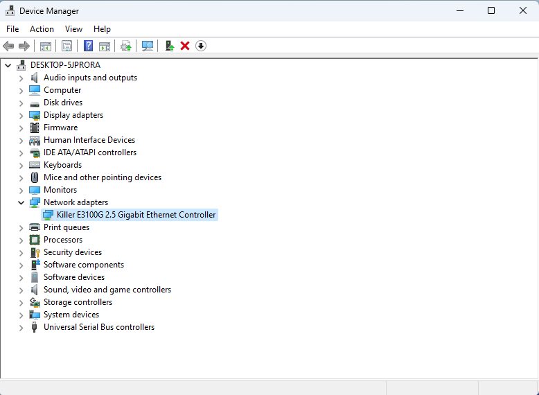
3. Go to the «Advanced” tab and set «Advanced EEE” to [Disabled]. 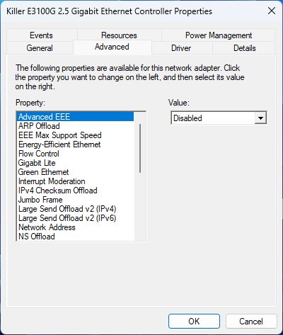
4. Set «Energy-Efficient Ethernet” to [Disabled]. 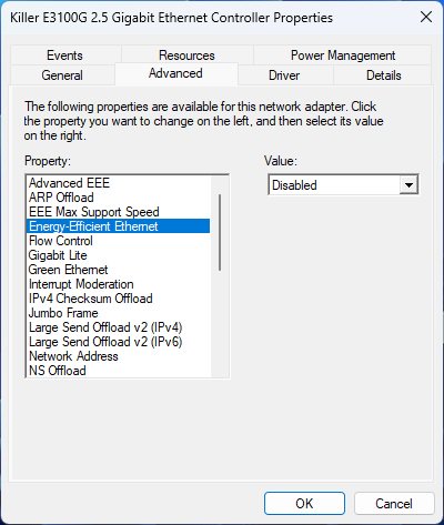
5. Set «Green Ethernet” to [Disabled]. 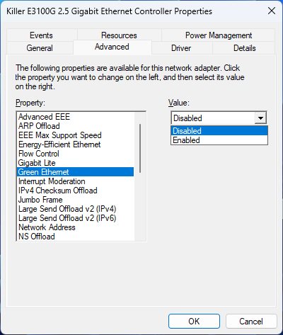
6. Set «Power Saving Mode” to [Disabled]. 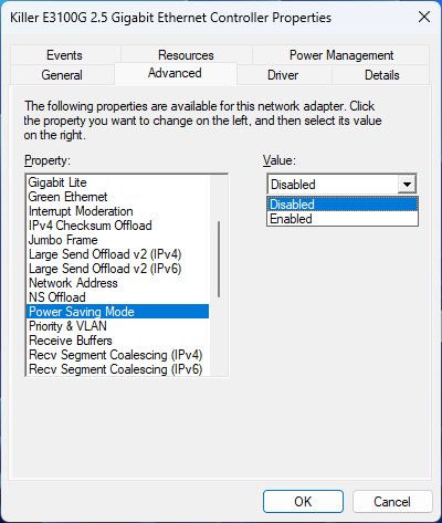
7. Fix «Speed & Duplex” at 2.5Gbps Full Duplex. 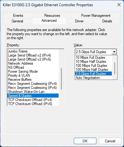
Answer:
Please update the vBIOS of your RX6800 CLP 16GO.
1. Go to AMD official website to download and install the latest official graphics card driver.
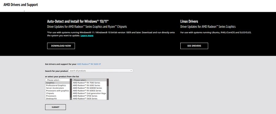
3. Run «insttool64.exe” as administrator. A command prompt window pop on and close immediately. It is a normal behavior.
4. Run Command prompt as administrator.
5. Enter the folder path to the extracted file and press [enter].
Default path and command:
cd C:\Users\[Username]\Downloads\VBIOS_L06_update\VBIOS update
*Please change the command if you change the download path.
6. Type command «Update.cmd” and press [enter].
Update procedure will start up. This mean the system is flashing the vBIOS. DO NOT turn off the system during the update.
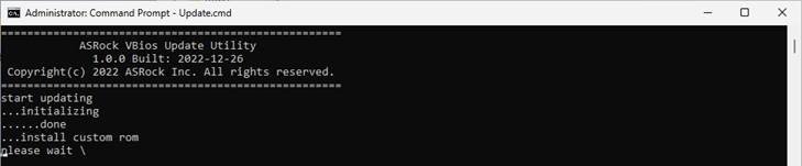
7. Once the flashing has finished, Command Prompt will report it as shown below. 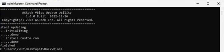
8. Please restart the system after flashing.
Answer:
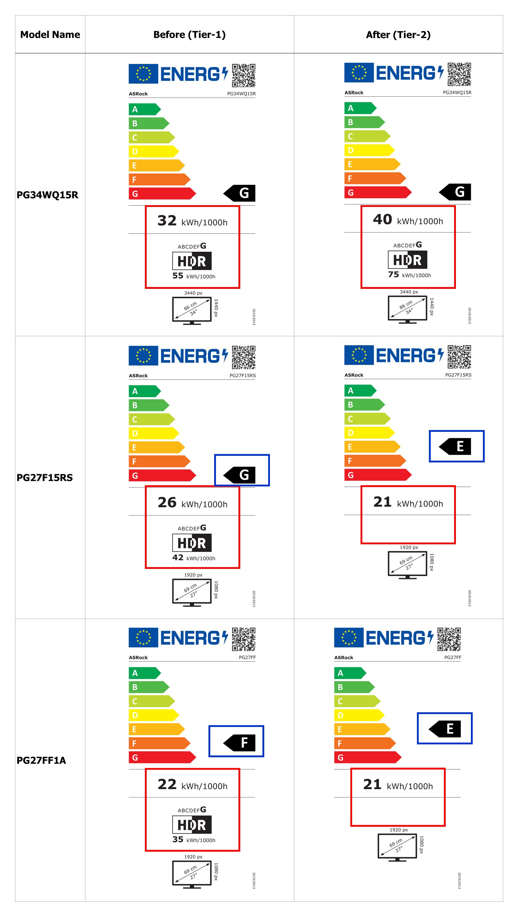
In response to the ErP Lot 5 Tier 2 eco-design requirements, ASRock updated the value of the European Union Energy Label on the website, which led to this situation.
If you notice that the value of the European Union energy label on the package of your purchased ASRock Gaming Monitor is different from the label information in the QR Code URL, this is absolutely normal. All the ASRock monitors are fully compliant with the ErP Lot 5 eco-design requirements.
The affected models are shown below for your reference.
Answer:
First check if your monitor supports HDR function. (High Dynamic Range)
You may check the product specifications on the ASRock website:
https://www.asrock.com/index.asp
E.g. ASRock Gaming Monitor PG27FF1A supports HDR function. 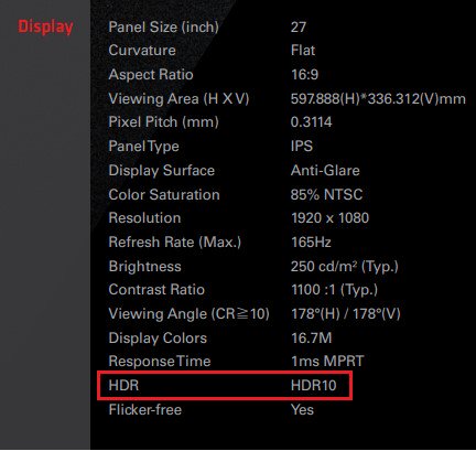
Settings under Windows 11:
1) Go to Settings> System> Display.
2) If your monitor supports HDR function, you may enable it. 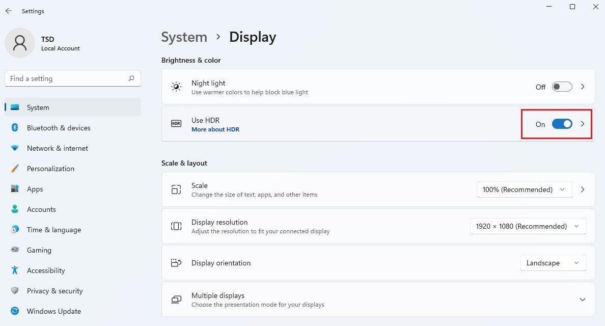
Settings under Windows 10:
1) Go to Settings> System> Display.
2) If your monitor supports HDR function, you may enable it. 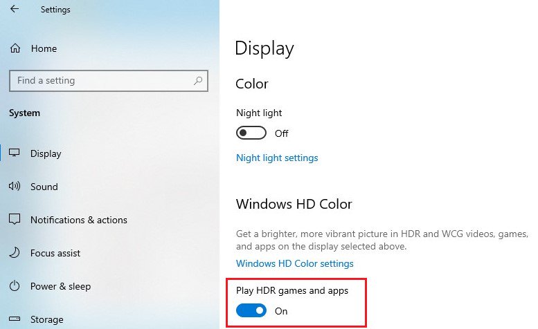
Hardware requirements
— Processor: Intel 7th gen. processor or later
— Graphics card: NVidia GTX 10 Series or later/AMD RX500 Series or later
Software requirements
— OS: Windows 10 (ver:1709 or later)
— Software: Movies & TV with HEVC Codec installed
— Microsoft Edge Browser, PowerDVD 17 or later and VLC v3.0 (64bit) or later
Answer:
We recommend using a graphic card that consumes up to 200 watt, and supports a discrete Dual slot Graphics card up to 20CM.
The Deskmeet supports CPUs that are up to 65W («Default TDP” or «Processor Base Power”). The peak power draw of a 65W CPU is about 200W.
The Deskmeet comes with a 500W PSU. So it is able to handle a graphic card with a power draw up to 200W.
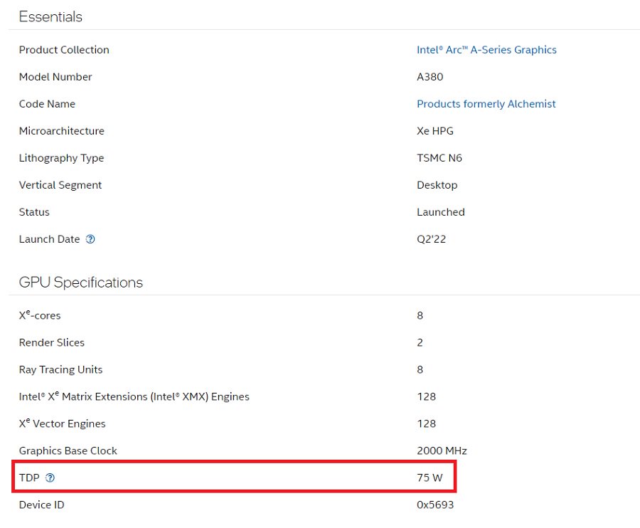
For the graphics card’s power consumption, please check the specifications provided by the graphic card’s vendor.
When checking the power consumption of the graphics card, please refer to the examples below. The power consumption is marked red here:
AMD 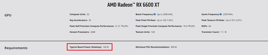
NVidia 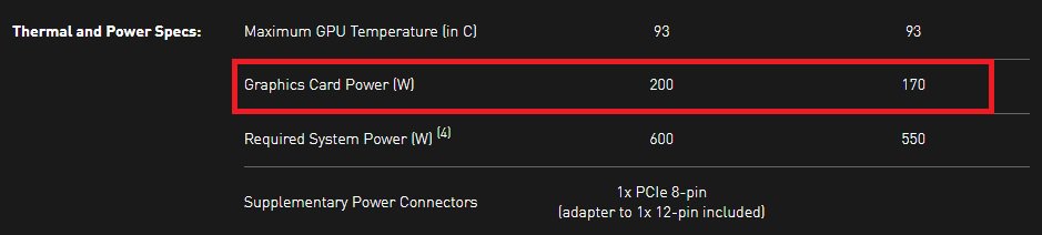
Intel
Answer:
First please determine which type of WiFi/Bluetooth(BT) module you can use on your motherboard. Second, if you want to use CNVi, you will need to check which generation of CNVi your motherboard supports.
Which type of WiFi/BT module is supported on your motherboard?
In general, there are 2 types of WiFi/BT modules that can be used via a Key E M.2 socket.
One type uses a regular PCIe connection (for WiFi) and USB connection (for Bluetooth) via the M.2 socket.
The other type uses CNVi, which is available on specific Intel platforms only:
https://www.intel.in/content/www/in/en/support/articles/000026155/wireless.html
On the Asrock website, please check the specifications of your motherboard to determine which type is supported on your motherboard. Here are some examples.
— 1 x M.2 Socket (Key E), supports type 2230 WiFi/BT PCIe WiFi module
This motherboard supports only WiFi/BT modules that use PCIe and USB via the Key E M.2 socket.
https://www.asrock.com/MB/Intel/H470M-HDVM.2/index.asp#Specification
— 1 x M.2 Socket (Key E), supports type 2230 Intel® CNVi (Integrated WiFi/BT)
This motherboard support only CNVi.
https://www.asrock.com/mb/Intel/J4005M/index.asp#Specification
— 1 x M.2 Socket (Key E), supports type 2230 WiFi/BT PCIe WiFi module and Intel® CNVi (Integrated WiFi/BT)
This motherboard support both types.
https://www.asrock.com/MB/Intel/B660M%20Pro%20RS/index.asp#Specification
Different generations of CNVi
If you would like to use CNVi, please note that there are different generations of CNVi. The table below shows which chipset supports which CVNi generation.
| Intel Chipset | Supported CNVi System Interface Type |
| Intel 300 series | M.2: CNVio |
| Intel 400 series | M.2: CNVio and CNVio2* *CNVio2 support only for Model Intel AX101, AX201, AX203. |
| Intel 500 series | |
| Intel 600 series | M.2: CNVio and CNVio2 |
Checking the specifications of WiFi/BT modules
To check the «System Interface Type” of your WiFi module, please visit Intel® ARK for further information.


Answer:
If you want to make a fresh Windows installation with Optane H10/H20 hybrid function, please refer to the following steps:
Step 1.
Make sure that H10/H20 Optane memory is installed in an M.2 socket which supports Optane. You can find the info by checking the storage section of the motherboard specifications page on ASRock’s website.
Step 2.
Enable the Hybrid Storage Detection and Configuration Mode in BIOS and press «F10” to save the settings.
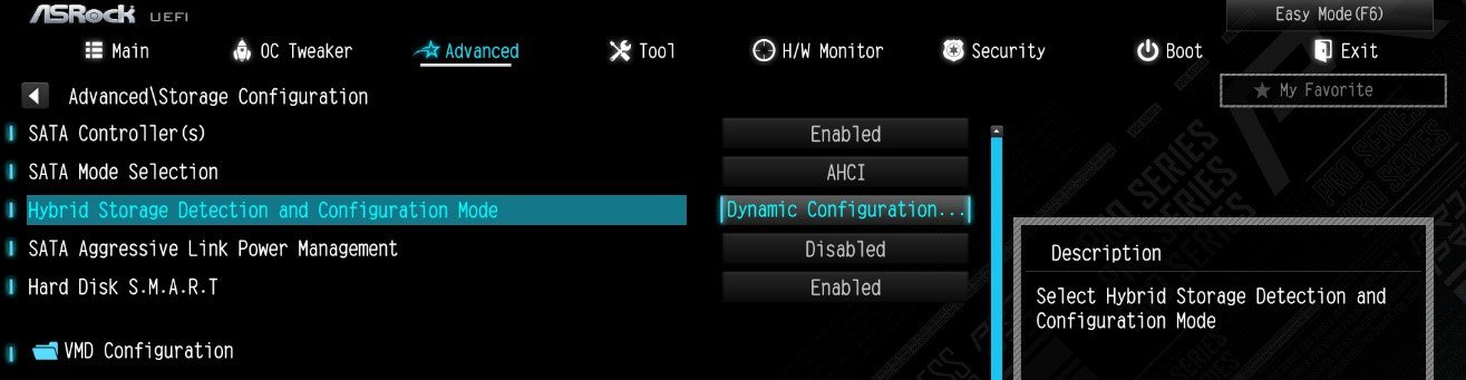
Advanced\Storage Configuration\Hybrid Storage Detection and Configuration Mode
Step 3.
Go to Advanced\Storage Configuration\VMD Configuration and set Enable VMD controller to [Enabled].
Then set Enable VMD Global Mapping to [Enabled]. Press F10 to save the changes and exit setup.
![Set Enable VMD Global Mapping to [Enabled]. Press F10 to save the changes and exit setup.](https://www.asrock.com/support/faq/167-4.jpg)
Installing Windows® on a VMD platform
After the BIOS setup, please follow the steps below.
Step 1.
Please download the «SATA Floppy Image” driver from ASRock’s website (https://www.asrock.com/index.asp). Unzip the file to a USB flash drive or copy the files from ASRock’s motherboard support CD.
Step 2.
Press at system POST to launch the boot menu and choose the item «UEFI: ” to install Windows® 10 64-bit / 11 64-bit OS
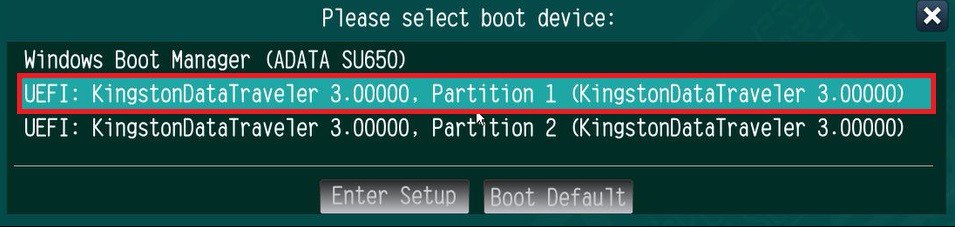 ” to install Windows® 10 64-bit / 11 64-bit OS»>
Step 3.
If during the Windows installation process the target drive is not available, please click .
Step 4.
Click
and locate the driver on your USB flash drive.
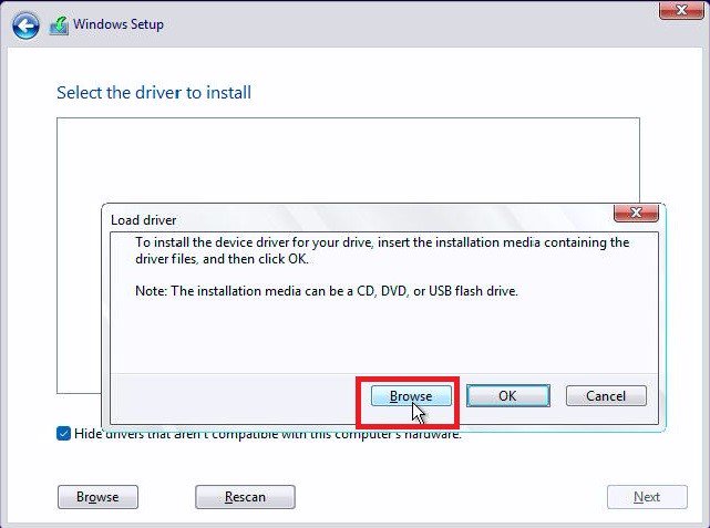
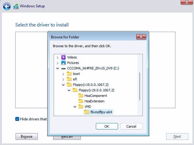
Step 5.
Select «Intel RST VMD Controller” and then click .
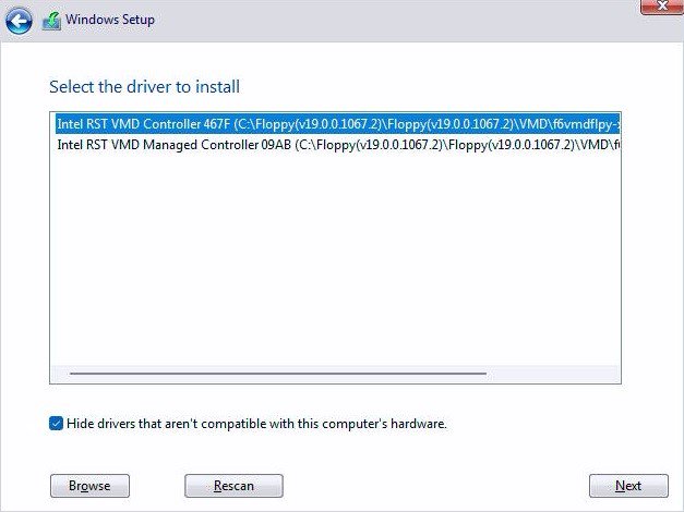 .»>
.»>
Step 6.
Select unallocated space and then click .
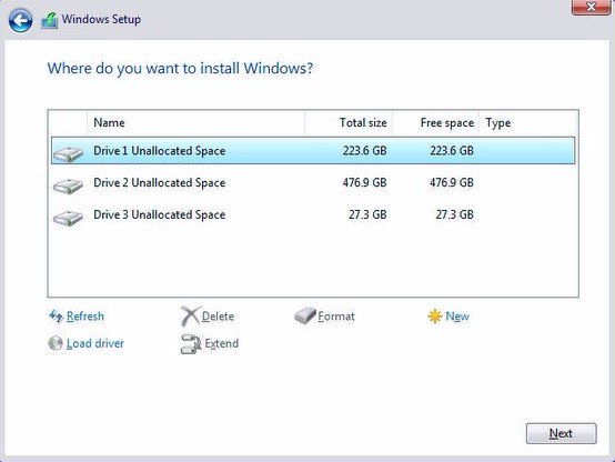
Step 7.
Please follow Windows’ installation instructions to finish the process.
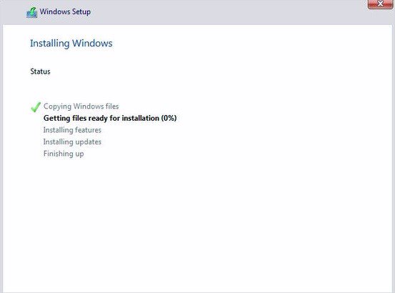
Step 8.
After the Windows installation is finished, please install the «Intel Rapid Storage Technology driver and utility” from ASRock’s website. https://www.asrock.com/index.asp
Step 9.
Launch the Intel® Optane™ Memory and Storage Management tool from the Microsoft store.
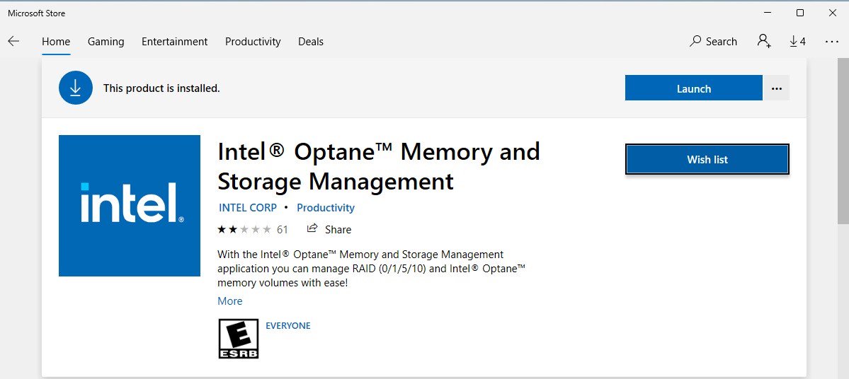
Step 10.
Select the drive which you want to accelerate. Enable Intel® Optane™ Memory. (One restart is required)
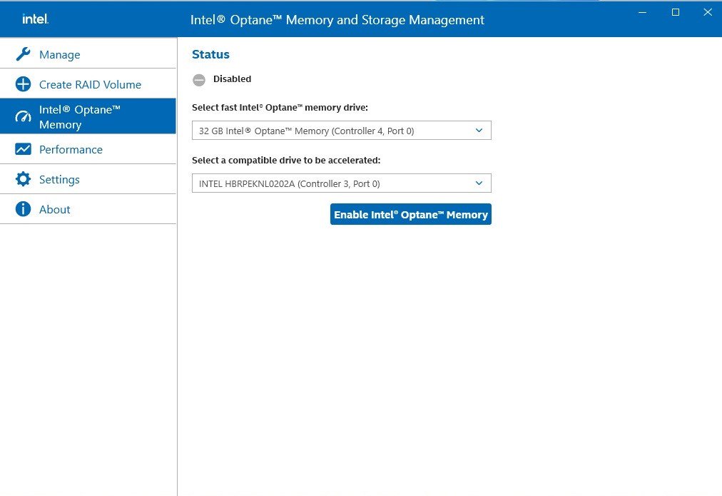
Step 11.
Erase all data on the Intel® Optane™ memory module and click
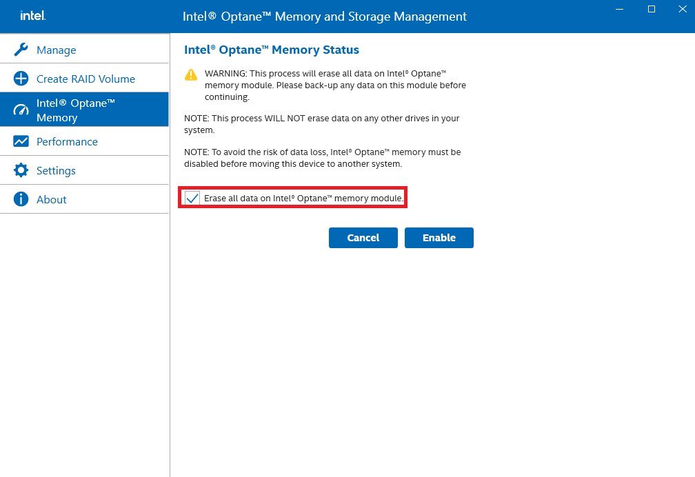
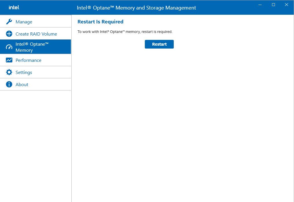
Step 12.
After the system has restarted, the Optane Management tool will show that Optane memory is enabled.
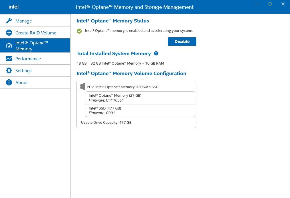
Answer:
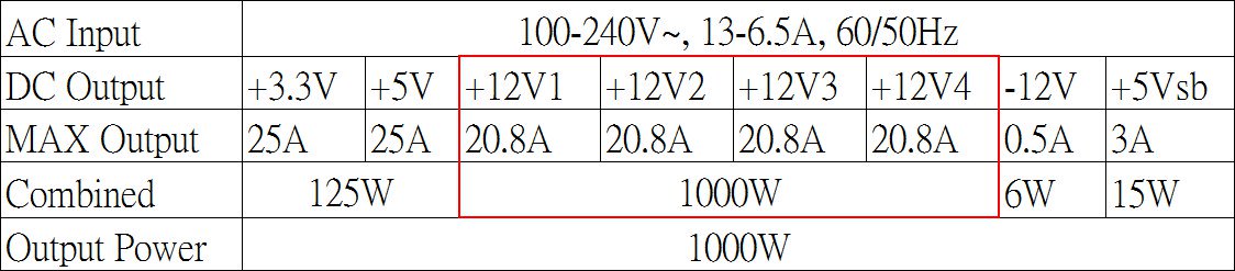
You can check the label on the power supply, it show the detailed specification of the power supply.
If you only see one «+12V” on your power supply, it means your power supply is «single rail” design.
For example. 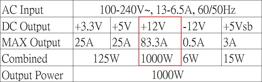
If you only see multiple»+12V” on your power supply, it means your power supply is «multi rail” design.
For example.
Answer:
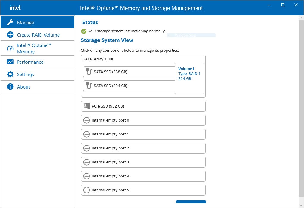
Please refer to the following steps to check the RAID configuration.
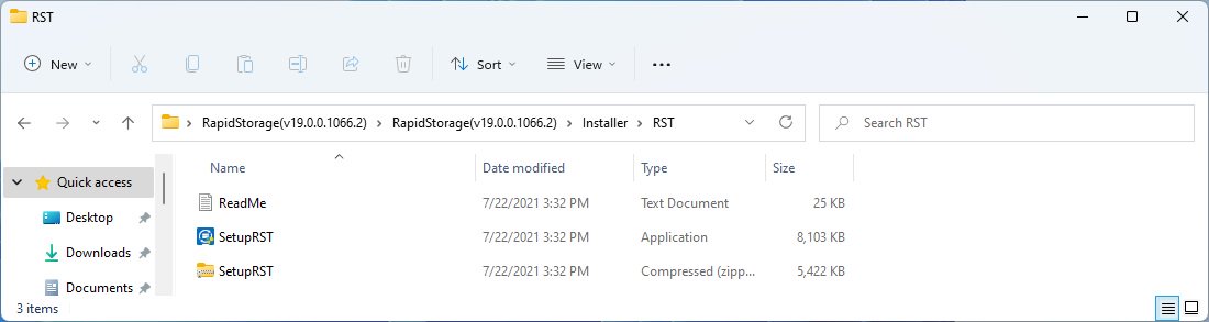
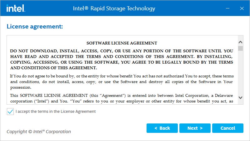
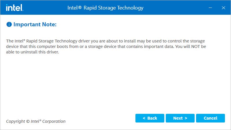
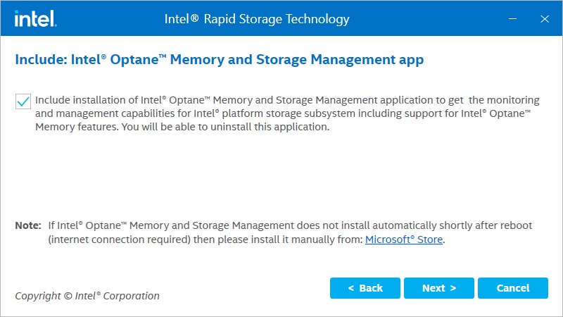
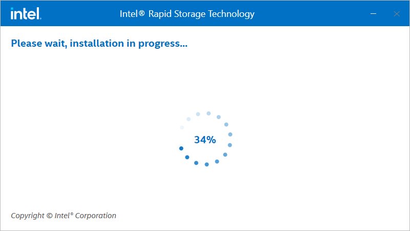
Step 1: Obtain the Intel(R) RST driver installation package and run the executable (SetupRST.exe).
*RST driver can be obtained via the download section of the product page on the ASRock website.
*Default settings and name of the driver may vary and is subject to change without notice.
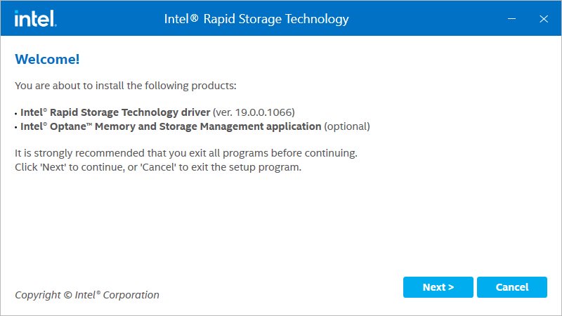
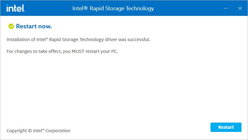
Step 2: Install using the default setting and reboot the computer.
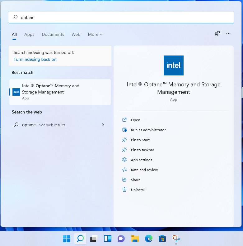
Step 3: From Windows desktop, find and launch the Intel® Optane(TM) Memory and Storage Management application.
Answer:
Some games use DRM (Digital Rights Management) protection. Please check for available updates for your game, where the DRM solution supports Alder Lake CPUs.
If the game development is discontinued and there is no update available for the DRM, please follow below steps to enable the «Legacy Game Compatibility Mode”.
Step 1.
Press [Del] or [F2] during the POST stage to boot into BIOS.
Step 2.
Press [F6] to enter «Advanced” mode and go to Advanced\CPU Configuration
Step 3.
Enable the «Legacy Game Compatibility Mode” in BIOS.
(The option is at the bottom of the CPU Configuration page) 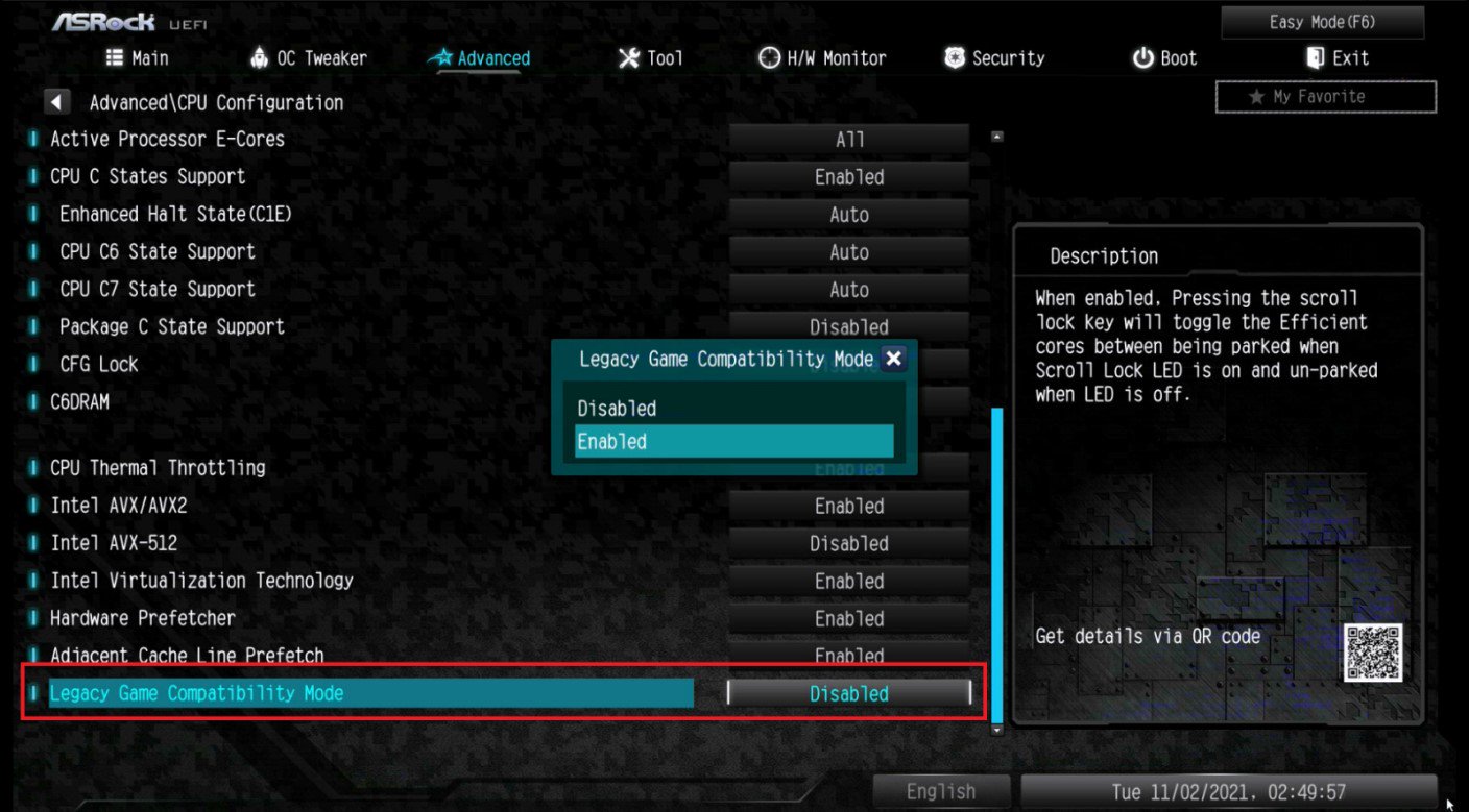
Step 4.
Press [F10] to save the setting and restart the system.
Step 5.
The [Scroll Lock] key on your keyboard is now a hotkey. It can be used to enable/disable the Intel E-core parking feature. Before starting a game outdated DRM protection, please press [Scroll Lock] within the OS to enable Intel E-core parking.
Answer:
Please follow the steps below to enable C.A.M. (Clever Access Memory) on H510 Pro BTC+.
Step 1.
Download BIOS 1.40 or later version from ASRock website and update the BIOS via Instant Flash.
https://www.asrock.com/MB/Intel/H510%20Pro%20BTC+/index.asp#BIOS
Step 2.
The C.A.M. (Clever Access Memory) option is supported when integrated graphics are disabled.
By default integrated graphics will be disabled when a PCIe graphics card is detected.
Please make sure the monitor is connected to the graphic card.
Step 3.
Please go to BIOS\Advanced\Chipset Configuration and enable «C.A.M. (Clever Access Memory)”. 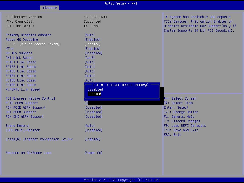
Step 4.
Press F10 to save the setting and restart.
Answer:
In order to use Secure Boot, the drive with the operating system must use GPT partition style. Please refer to below steps to check the partition style.
Step 1: Right-click the Windows button on the desktop and select «Disk Management”. 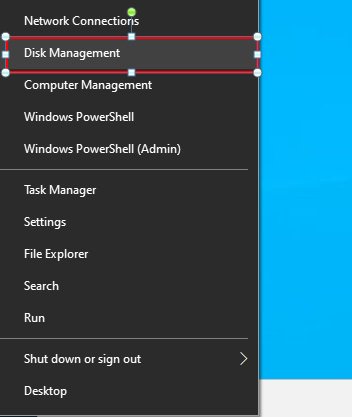
Step 2: Right-click the disk where Windows is installed and select the «Properties”. 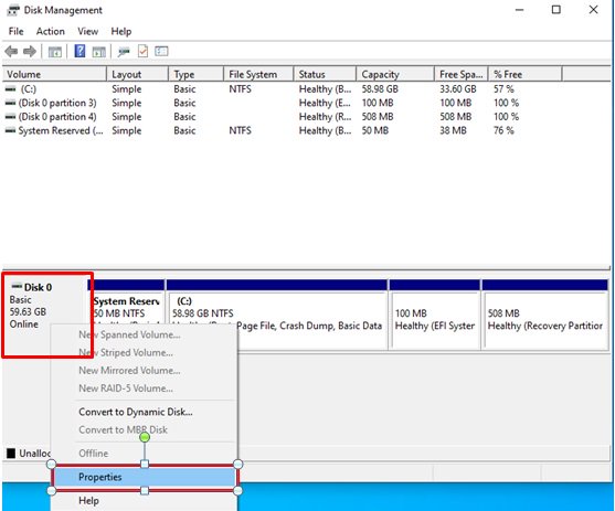
Step 3: Click the «Volumes” tab and check if the partition style is «GPT”. 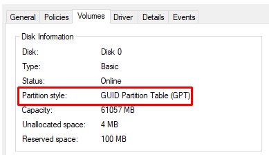
Step 4: If the partition style is «MBR”, please make a backup of important data on the system and refer to steps 5 — 7 to convert the partition style to GPT. 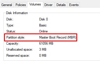
Step 5: Type «CMD» in the Windows search bar, right-click on «Command Prompt” and choose to run as administrator. 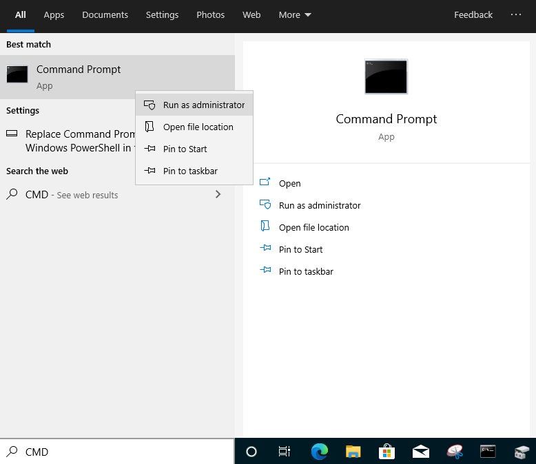
Step 6: Type the command «mbr2gpt /convert /allowFullOS” to convert the partition style and press [Enter]. 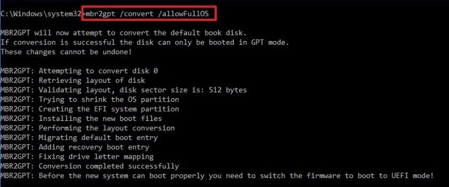
Step 7: Restart the system and the BIOS Mode/Partition style will be converted to UEFI/GPT.
Question (505): Why does the ASRock Timing Configurator show strange values, and how can I use this OC software under Windows 11? 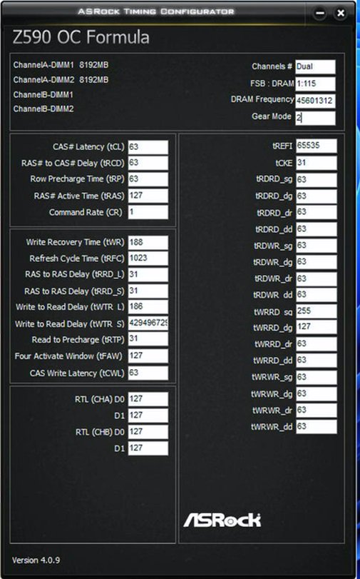 (10/1/2021)
Question: Why does the ASRock Timing Configurator show strange values, and how can I use this OC software under Windows 11? (10/1/2021)
Answer:
Microsoft® Windows 11® has a security function called «Memory integrity”. This function can prevent attacks from inserting malicious code into high-security processes, but it will interfere with the ability to read sensor values and affect the function of OC software.
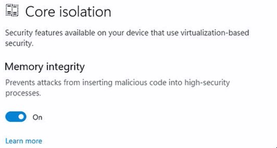
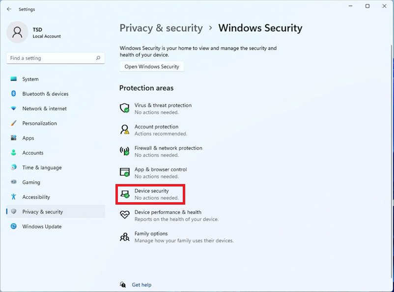
We recommend temporarily disabling this function when you would like to use OC software. Please refer to the following steps to deactivate it.
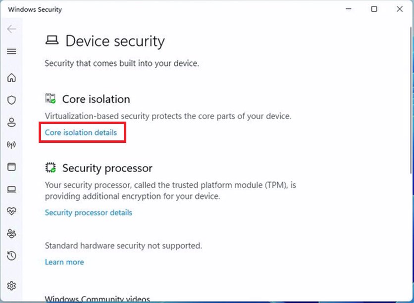
Step.2 Press «Core isolation details”.
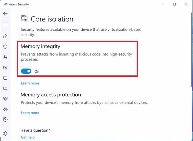
Step.3 Disable «Memory integrity” and restart the system to apply the setting.
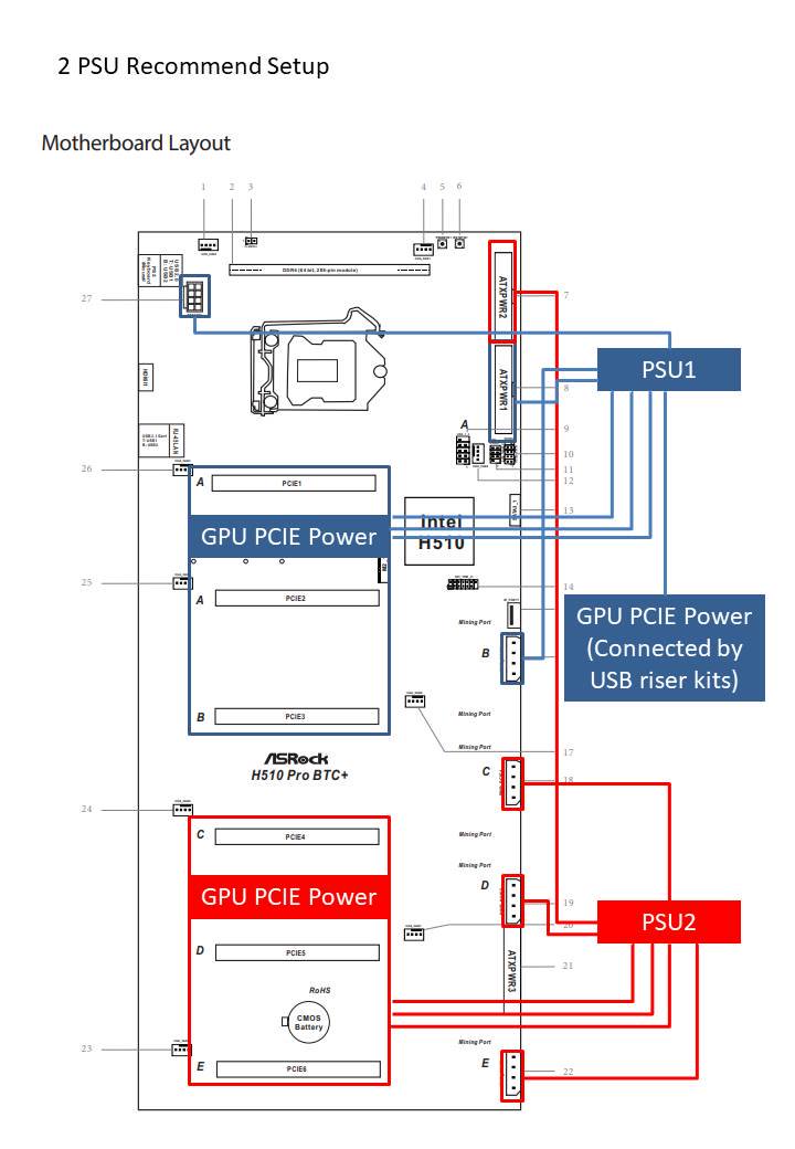
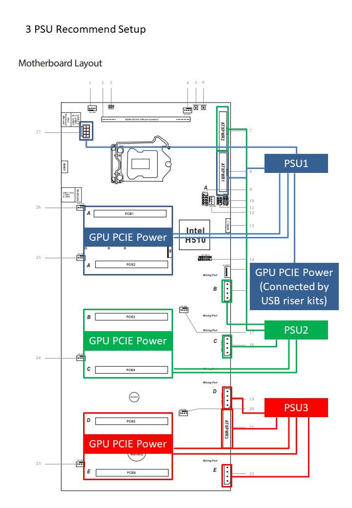
Answer:
Please refer to the images below.
[Recommended connections when using two power supplies]
[Recommended connections when using three power supplies]
Answer:
Please refer to the following for the Bitlocker status, Suspend / Resume Bitlocker and TPM version information.
[Bitlocker Drive Encryption]
(1) Bitlocker status
To check the Bitlocker status, please refer to the following steps.
Step 1 – Please go to Control Panel > System and Security > Bitlocker Drive Encryption
Step 2 – The Bitlocker status is shown under the red-boxed section as in the following picture.
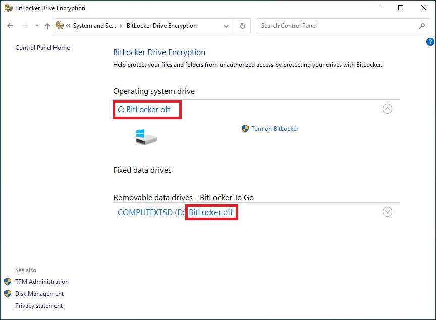
(2) Suspend / Resume Bitlocker
The bitlocker feature can be suspended and resumed when Bitlocker Drive Encryption is enabled.
Step 1 – Please go to Control Panel > System and Security > Bitlocker Drive Encryption
Step 2 – Click the «Suspend protection” as shown in the red-boxed below.

Step 3 – Click the «Resume protection” as shown in the red-boxed below.
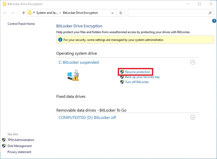
[TPM Version]
To check the TPM version, please refer to the following steps.
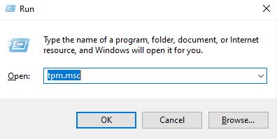
Step 1 – Press hotkeys «Windows + R” together to open the Run box.
Step 2 – Type in «TPM.MSC» to open the Windows TPM management tool.
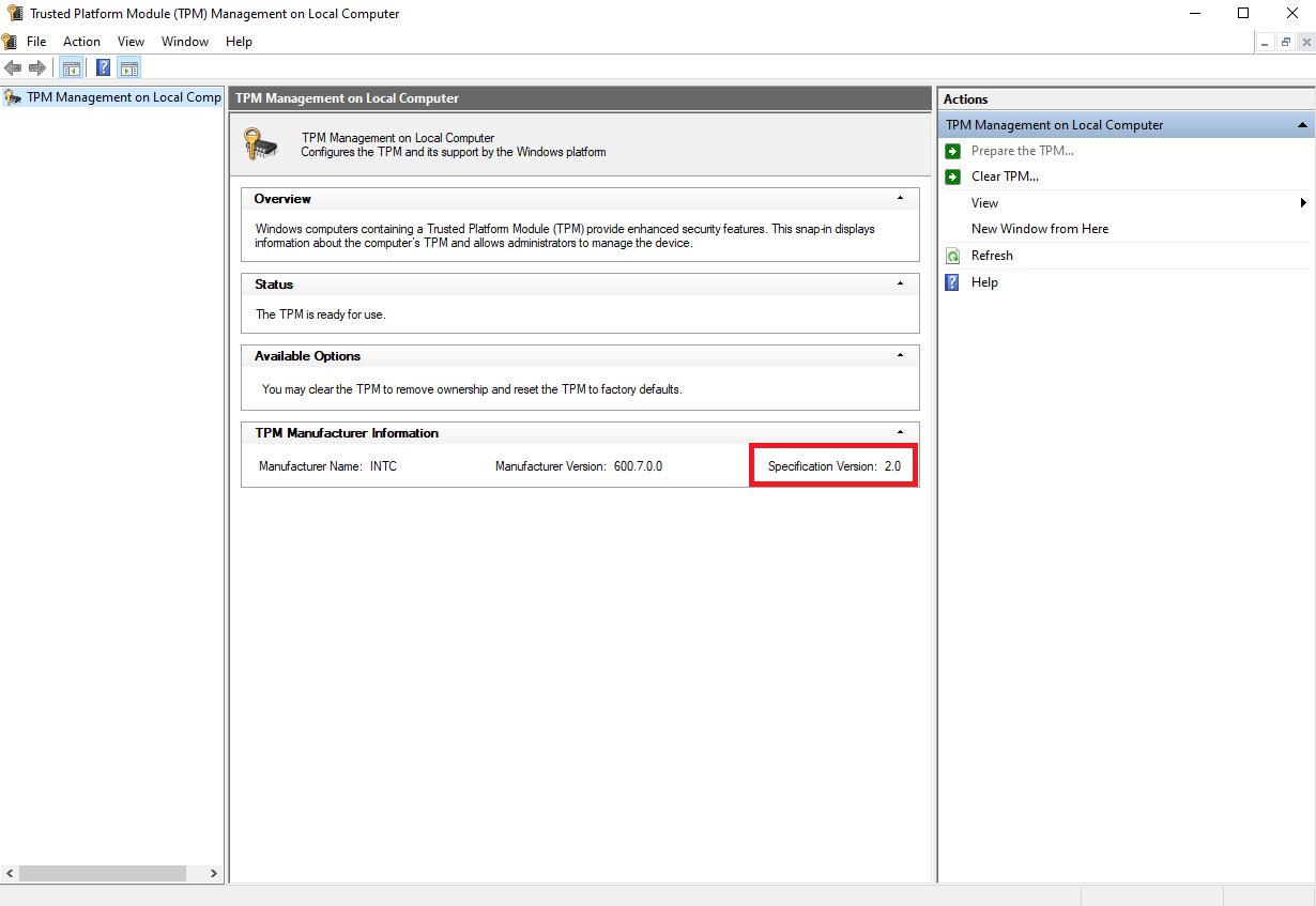
Step 3 – The TPM Management window will open.
Information such as TPM version can be found in the TPM Management window.
Answer:
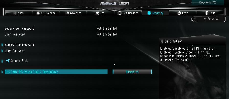
No, please enabled [Intel® Platform Trust Technology (Intel® PTT)] or [AMD CPU fTPM] feature under UEFI BIOS. It supports the TPM2.0 feature without TPM2.0 hardware module.
ASRock Intel Platform
For the new Microsoft® Windows 11 installation, we recommend disabling the CSM setting before using the Intel® PTT.
Supported platform.
| Series | Supported Platform |
| Intel MSDT | Intel 300 series or later plaform |
| Intel HEDT | Intel X299 or later platform |
| Intel SOC | Gemi Lake or later platform |
* Intel® PTT is supported. The actual support may be varied based on official release of Windows 11 by Microsoft®.
BIOS option
(a) Go to «Security page” to find the «Intel® Platform Trust Technology” option.
(b) Enabled «Intel® Platform Trust Technology” under UEFI BIOS
ASRock AMD Platform
For the new Microsoft® Windows 11 installation, we recommend disabling the CSM setting before using the AMD CPU fTPM.
Supported platform.
| Series | Supported Platform |
| * AMD AM4 | AMD 300 series or later plaform |
| AMD AM5 | AMD 600 series or later platform |
| * AMD HEDT | X399, TRX40, WRX80 |
* AMD CPU fTPM is supported. The actual support may be varied based on official release of Windows 11 by Microsoft®.
BIOS option
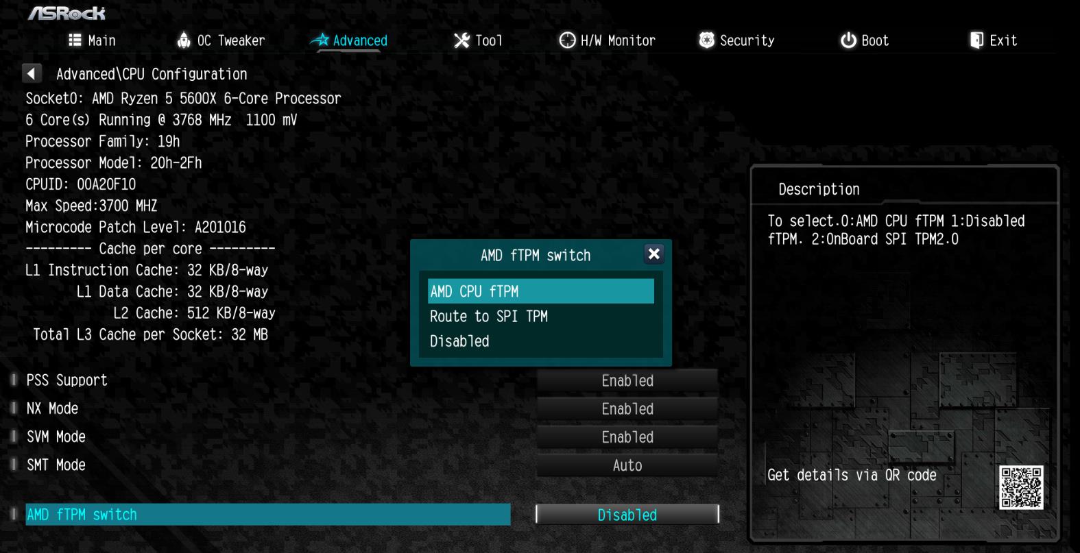
(a) Go to «Advanced» \ «CPU Configuration» page to find [AMD fTPM switch].
(b) Adjust «AMD fTPM switch» option to [AMD CPU fTPM].
11 th Generation
10 th Generation
Z590 OC Formula
B560M Steel Legend
11 th Generation
10 th Generation
Z590 PG Velocita
Z590 Extreme WiFi 6E
Z590 Steel Legend WiFi 6E
Z590 Steel Legend
Z590 Phantom Gaming 4/ac+
Z590 Phantom Gaming 4/ac
Z590 Phantom Gaming 4
H570 Phantom Gaming 4
H570 Steel Legend
Z590M Phantom Gaming4
Z590 Phantom Gaming-ITX/TB4
B560 Steel Legend
Answer:
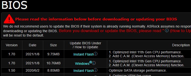
Step 1: On the ASRock website please find the BIOS download page for you motherboard.
Check the descriptions to see if C.A.M. is supported already.
Intel 500-series models support C.A.M. since the first version.
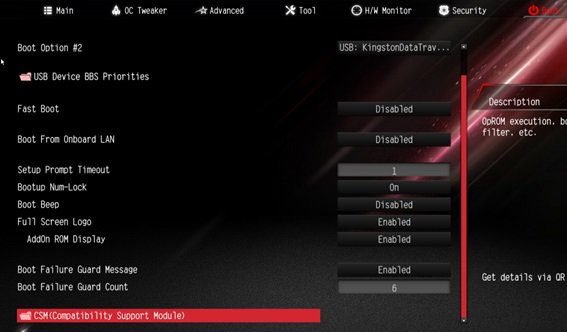
Step 2: While the system is starting press «DEL” to boot into BIOS setup and go to BIOS\Boot\CSM.
If you cannot find the CSM menu then please set «Fast Boot” to «Disabled”.
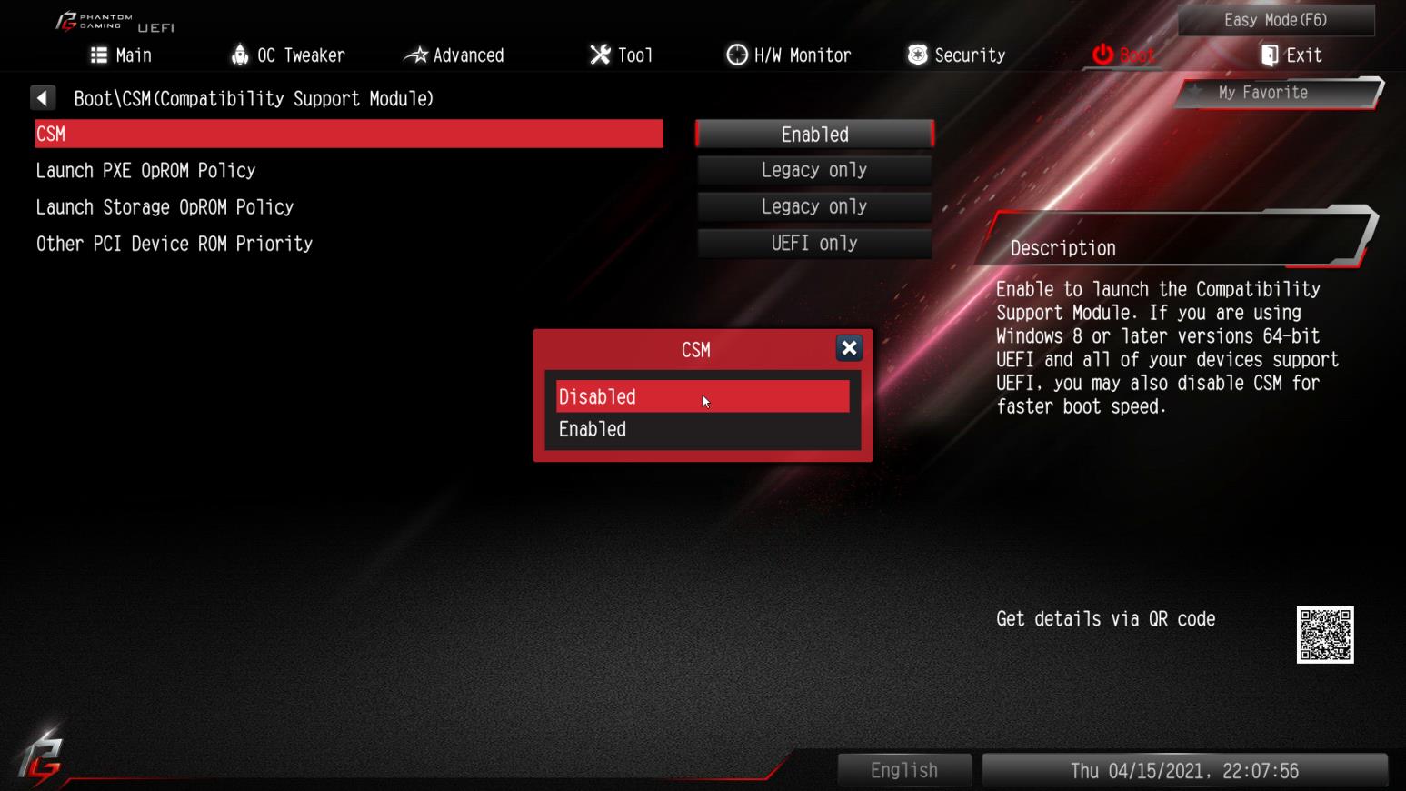
Step 3: In BIOS\Boot\CSM please set «CSM” to «Disabled”.
Step 4: Go to BIOS\Advanced\Chipset Configuration and set «Above 4G Decoding” to «Enabled”.
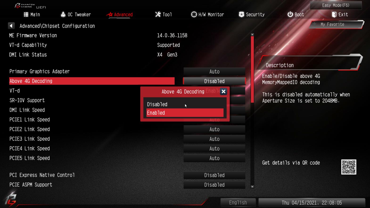
Step 5: After step 4, the option «C.A.M” will appear below the option «Above 4G Decoding”.
Please set it to «Enabled”.
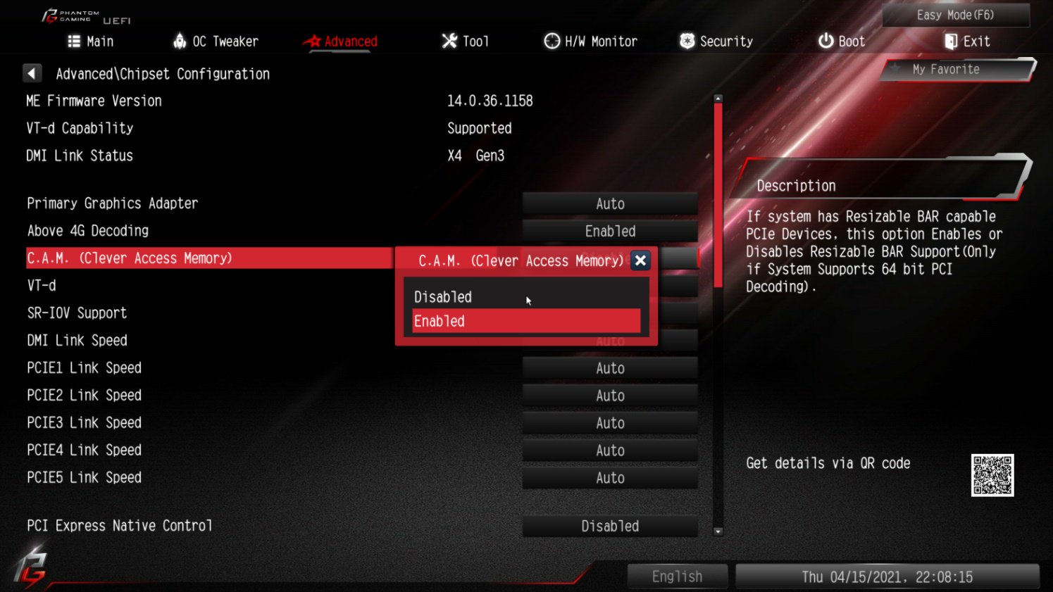
Step 6: Press «F10” to save the settings and restart the system.
Answer:
Please follow the steps below.
Step 1: Disconnect the PSU from the motherboard.
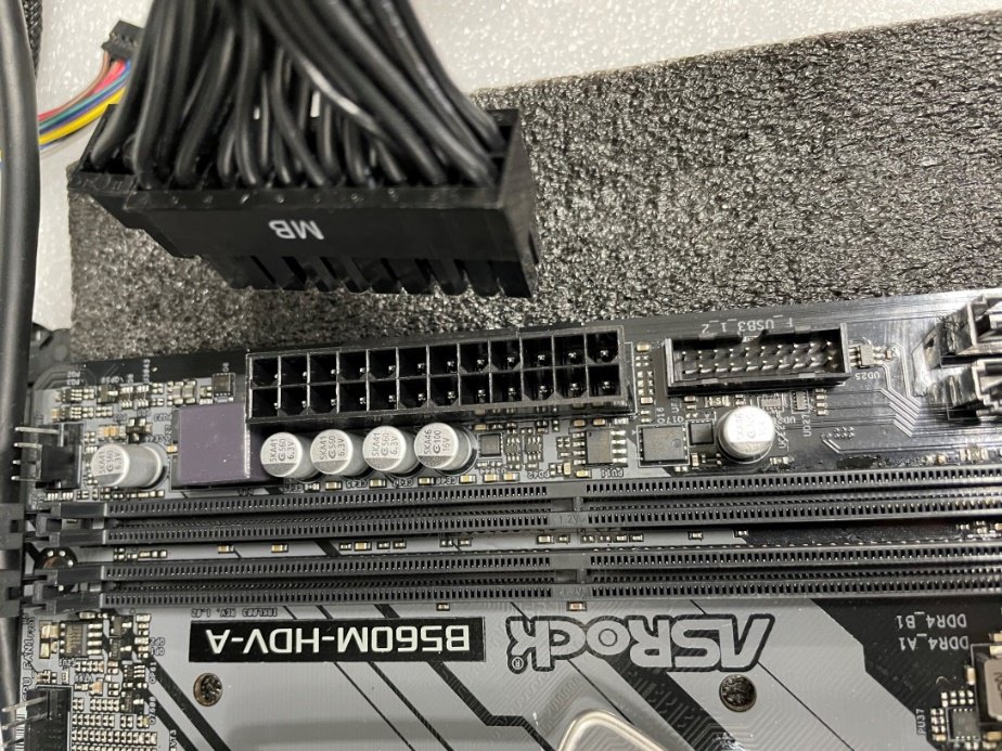
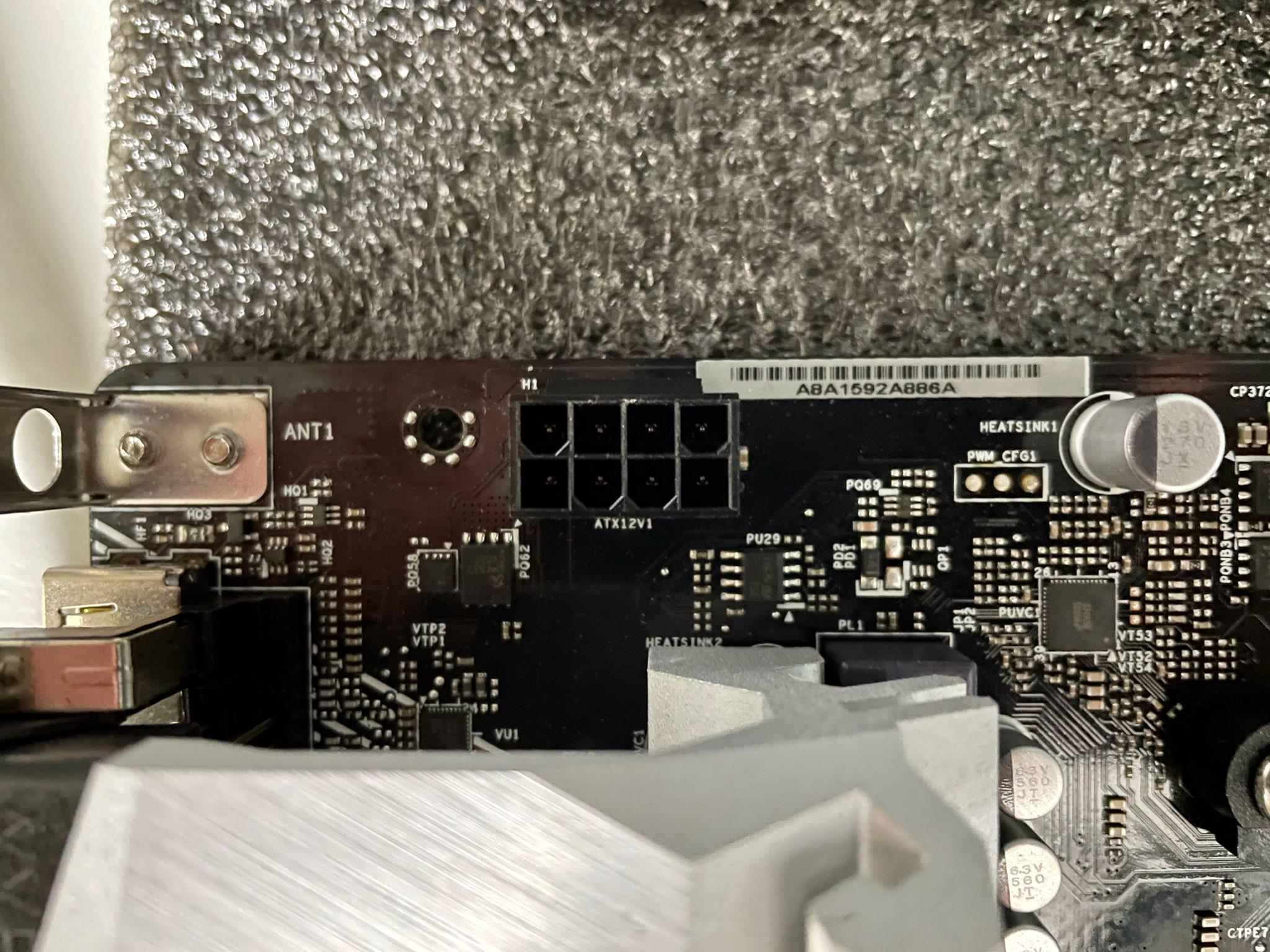
Step 2: Find the CLRMOS header by referring to the motherboard user manual.
Below picture shows what the header should look like.
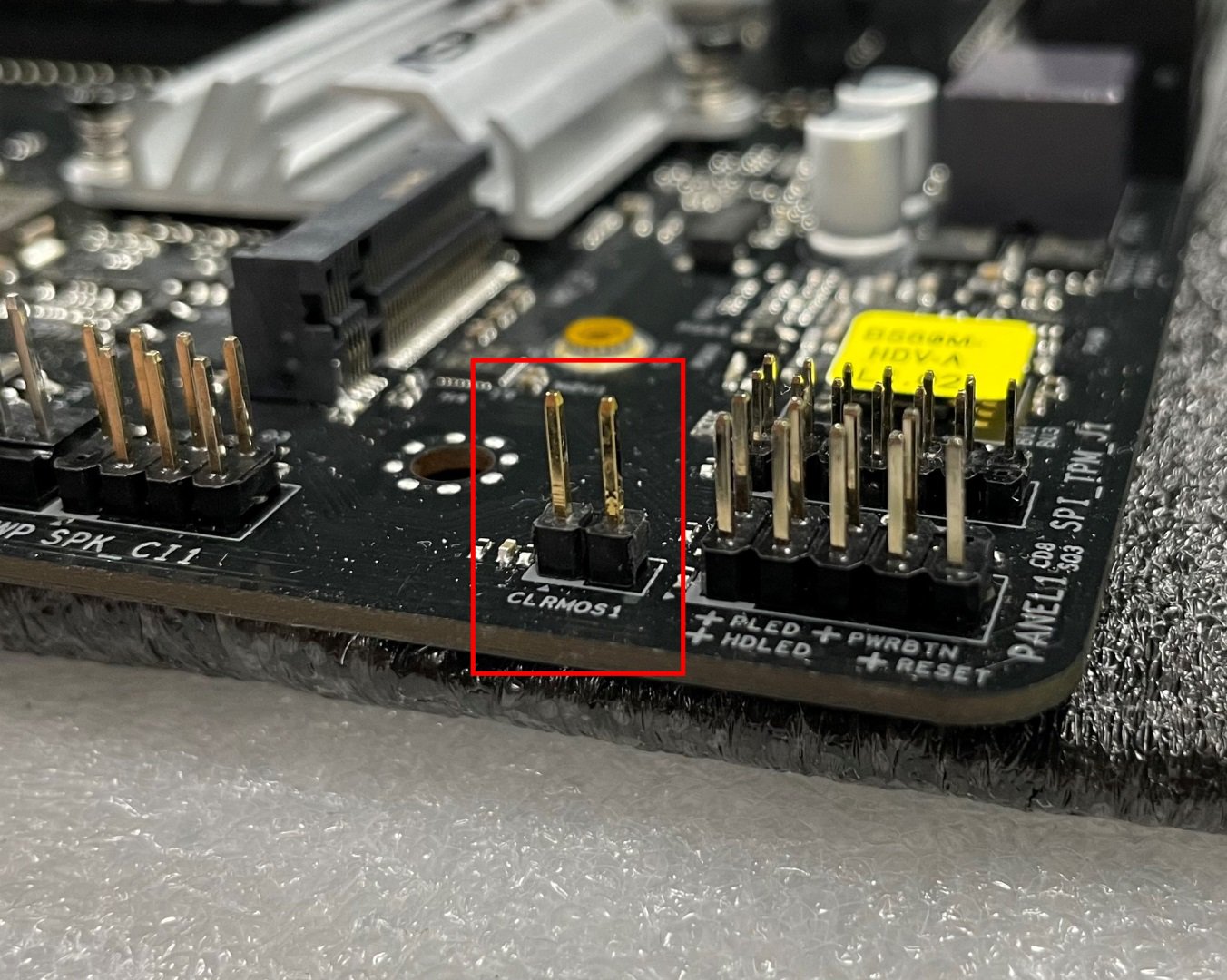
Step 3: Use a conductive metal object to short the CLRMOS header for at least 30 seconds. You can use for example a paperclip, key, coin or a screwdriver.
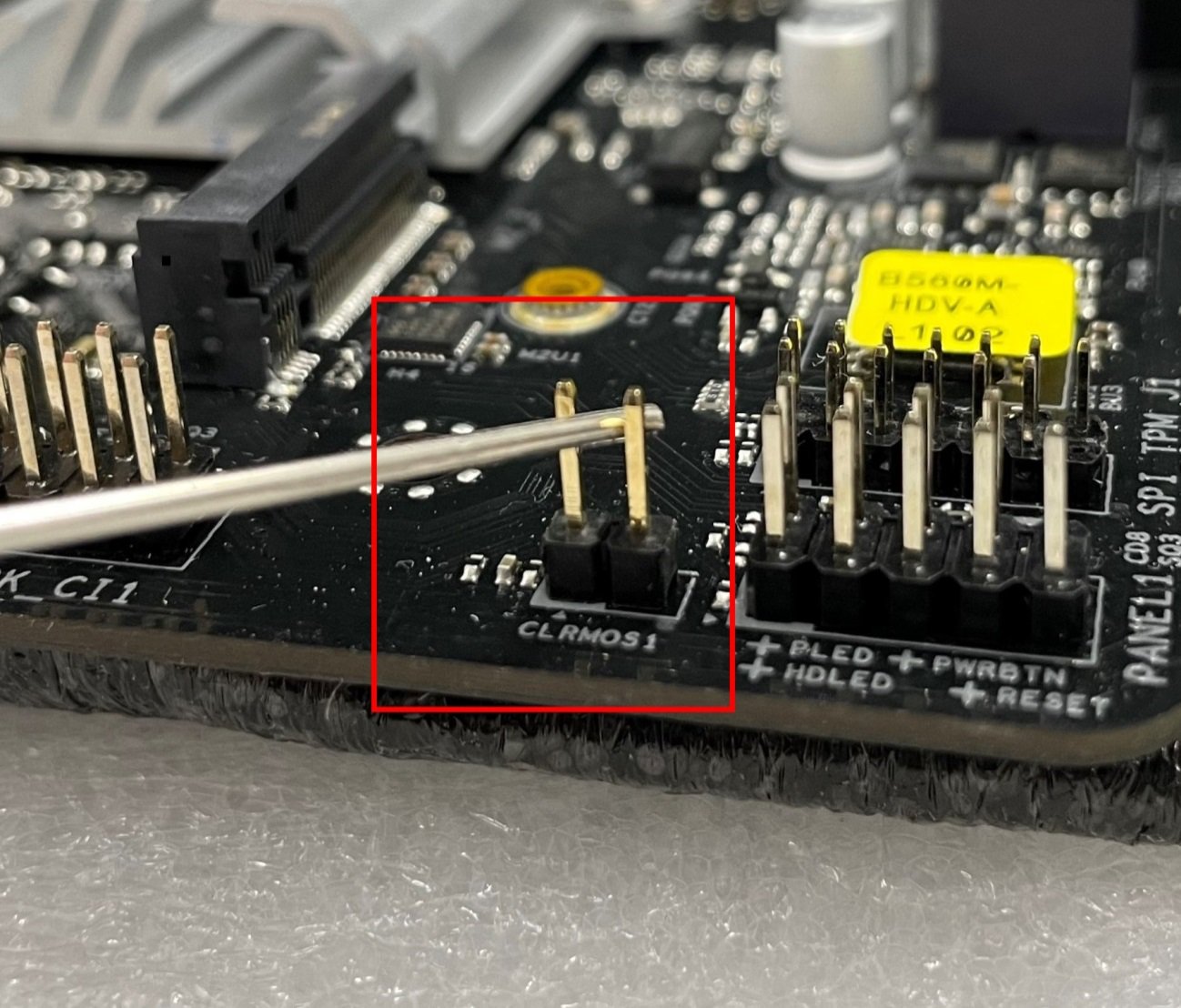
Step 4: Remove the metal object from the CLRMOS header and then wait at least 5 more minutes.
Step 5: After 5 minutes please reconnect the PSU and power on the system.
Answer:
Please flash the RGB controller firmware by following the steps below.
Step 1.
Download the firmware file from ASRock website and extract the compressed file.
Step 2.
Execute «UpdateFW.cmd” to update the RGB controller firmware. 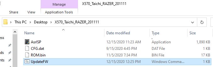
Step 3.
After step 2 please wait for 10 seconds or so and the firmware flash will finish. 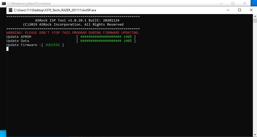
Step 4.
After the message «update firmware SUCCESS” is shown please restart your system.
Answer:
Your motherboard might be using a semi-passive mode for this fan.
In this mode the fan will not spin at lower temperatures, and only become active at higher temperatures. This is normal. If you want to let the fan spin, you can select a different mode for the fan in BIOS.
Path: BIOS\H/W Monitor\SB_FAN1 Setting
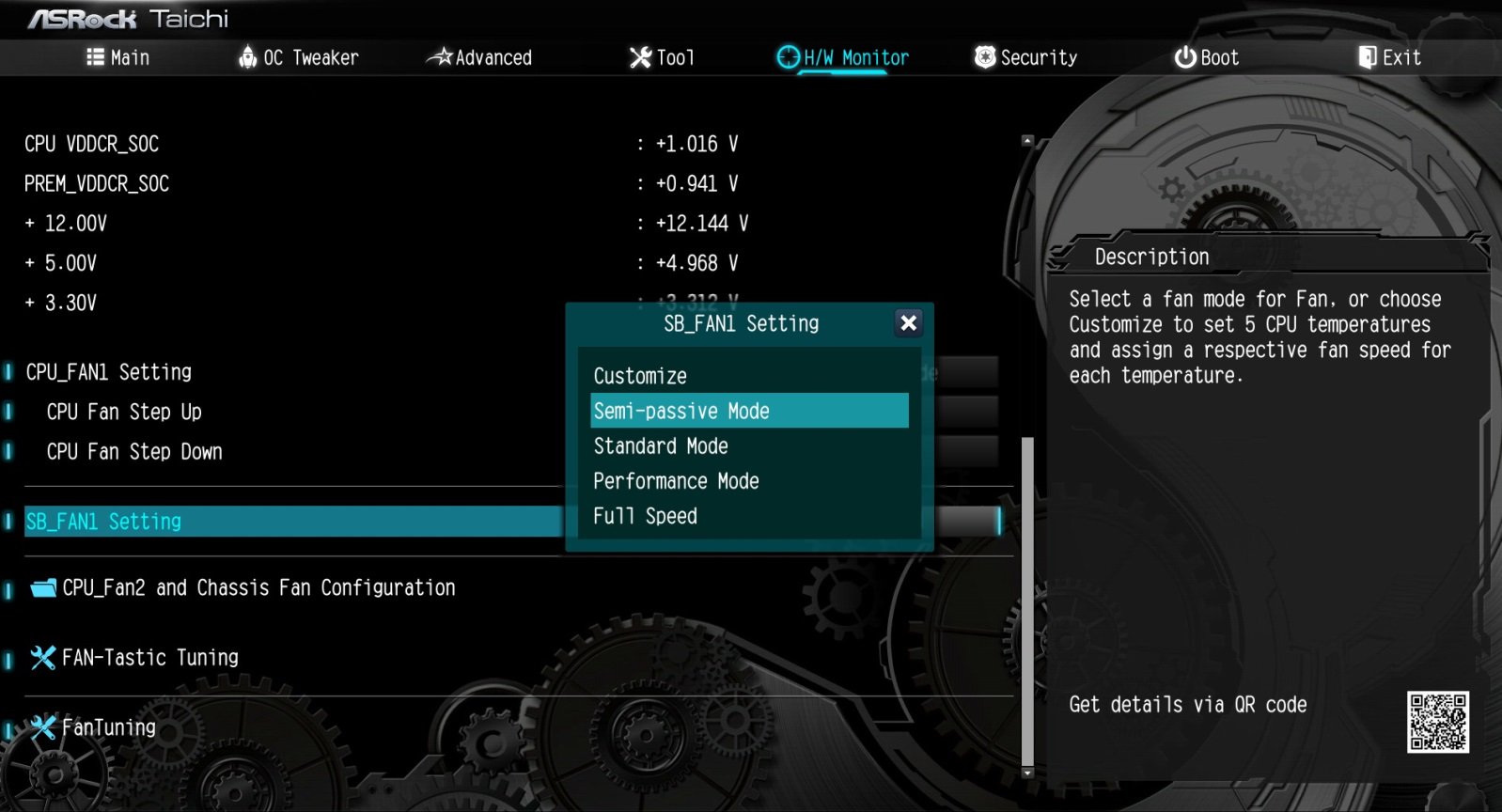
Answer:
To enable an Optane H10 while another Intel M.2 SSD is installed, please refer to the following steps:
Step 1. Make sure that H10 Optane memory is installed in the Optane supporting M.2 socket by checking the storage section of the motherboard web page.
Step 2. Download and install the Intel RST driver version 18.0.0.1135 (or newer) from the link below:(A few restarts will be required)
Link: https://download.asrock.com/Drivers/Intel/Optane/Optane(v18.0.0.1135).zip
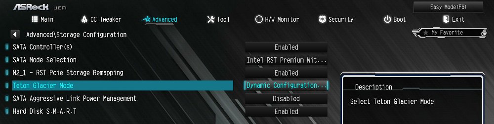
Step 4. Enable the Teton Glacier Mode in BIOS and press F10 to save the settings.
Advanced\Storage Configuration\Teton Glacier Mode\Dynamic Configuration for Hybrid Storage Device Enable
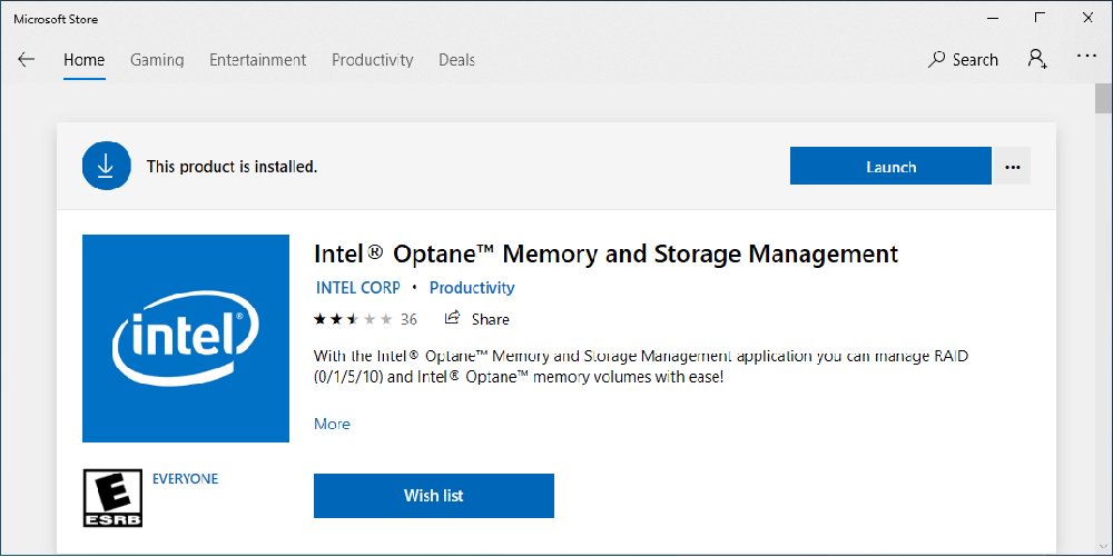
Step 5. Launch the Intel Optane Memory and Storage Management tool from the Microsoft store.
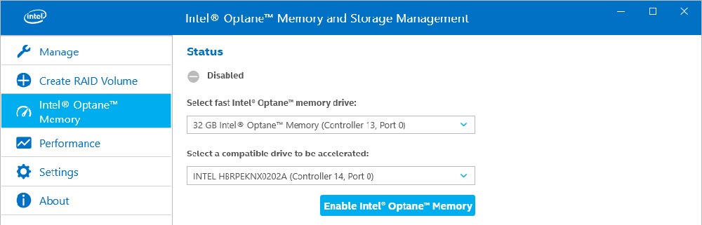
Step 6. Enable Optane memory. (One restart is required)
Step 7. After the system has restarted, the Optane Management tool will show Optane memory is enabled.
Answer:
Please refer to the following flow chart for basic debugging.
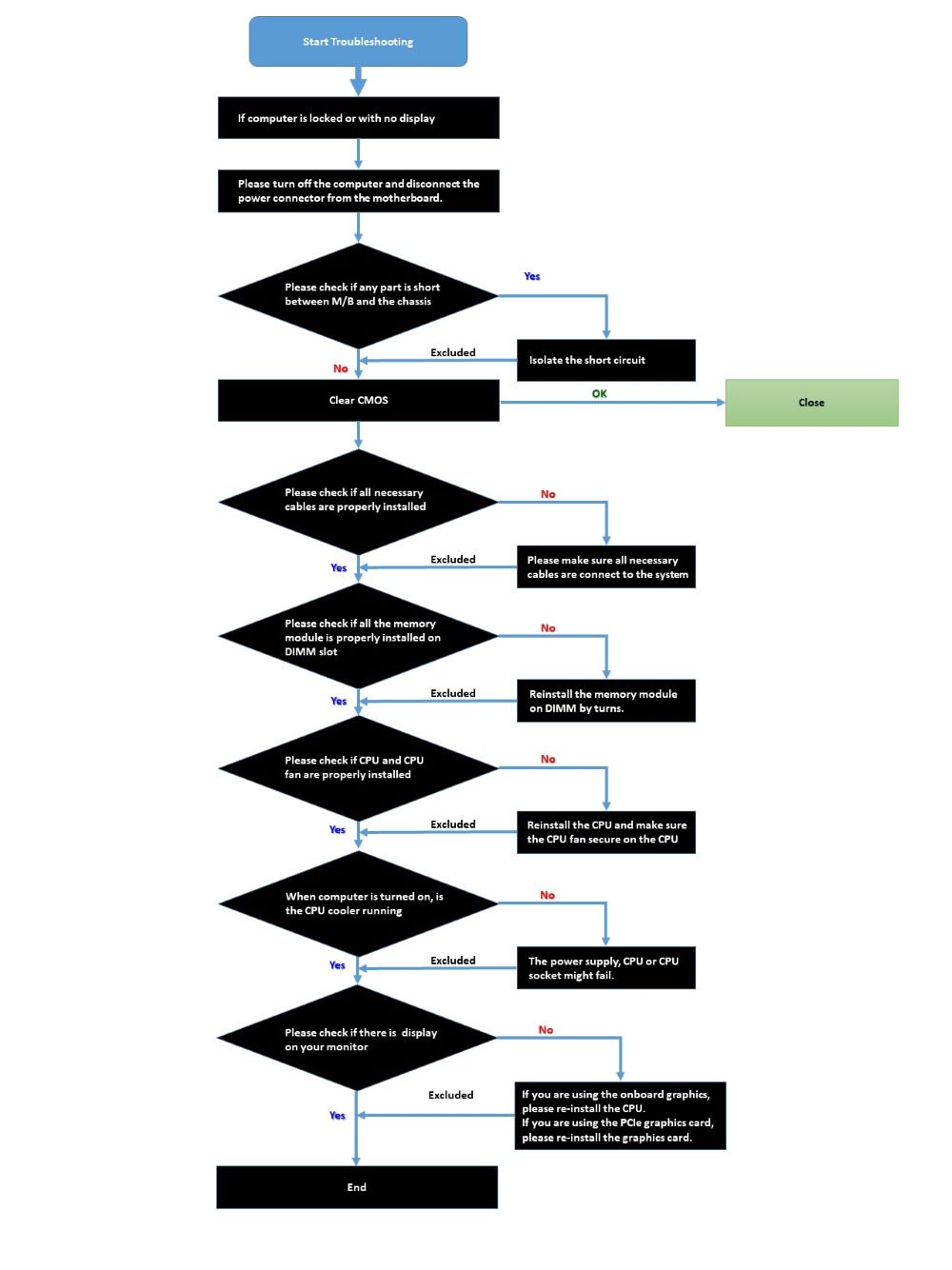
If the procedure above does not help to solve your problem, please contact the seller or local dealer for help. Or go to Support\Contact Technical Support to submit your question. Then our customer service staff will reply to you as soon as possible.
Answer:
Please make sure to use identical PCIE SSDs that are the same type and volume.
Follow the steps below to adjust the BIOS settings to configure the PCIe RAID.
STEP 1. Enter the UEFI Setup Utility by pressing or hotkey during the post screen.
STEP 2. Go to Advanced -> Storage Configuration and set SATA Mode Selection to [RAID Mode].
STEP 3. Go to Boot -> CSM and set Launch Storage OpROM policy to [UEFI only].
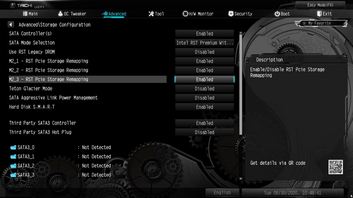
STEP 4. Adjust the M.2 slots — RST PCie Storage Remapping that you’ve installed PCIE SSDs to [Enabled]. Press to save the settings and exit setup.
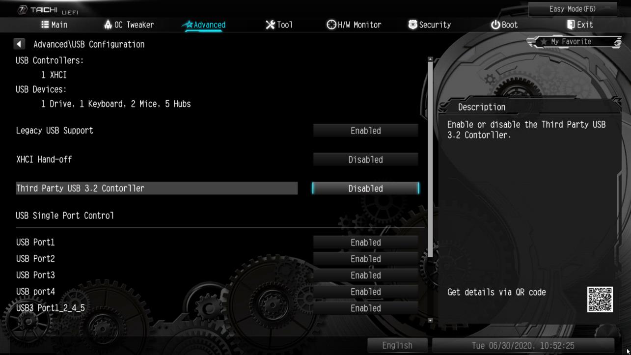
STEP 5. Go to Advanced -> USB Configuration and set Third Party USB 3.2 Controller to [Disabled]. Press to save the configuration changes and exit setup. Caution: After disabling the Third Party USB3.2 Controller, the onboard Type-C port will be turned off.
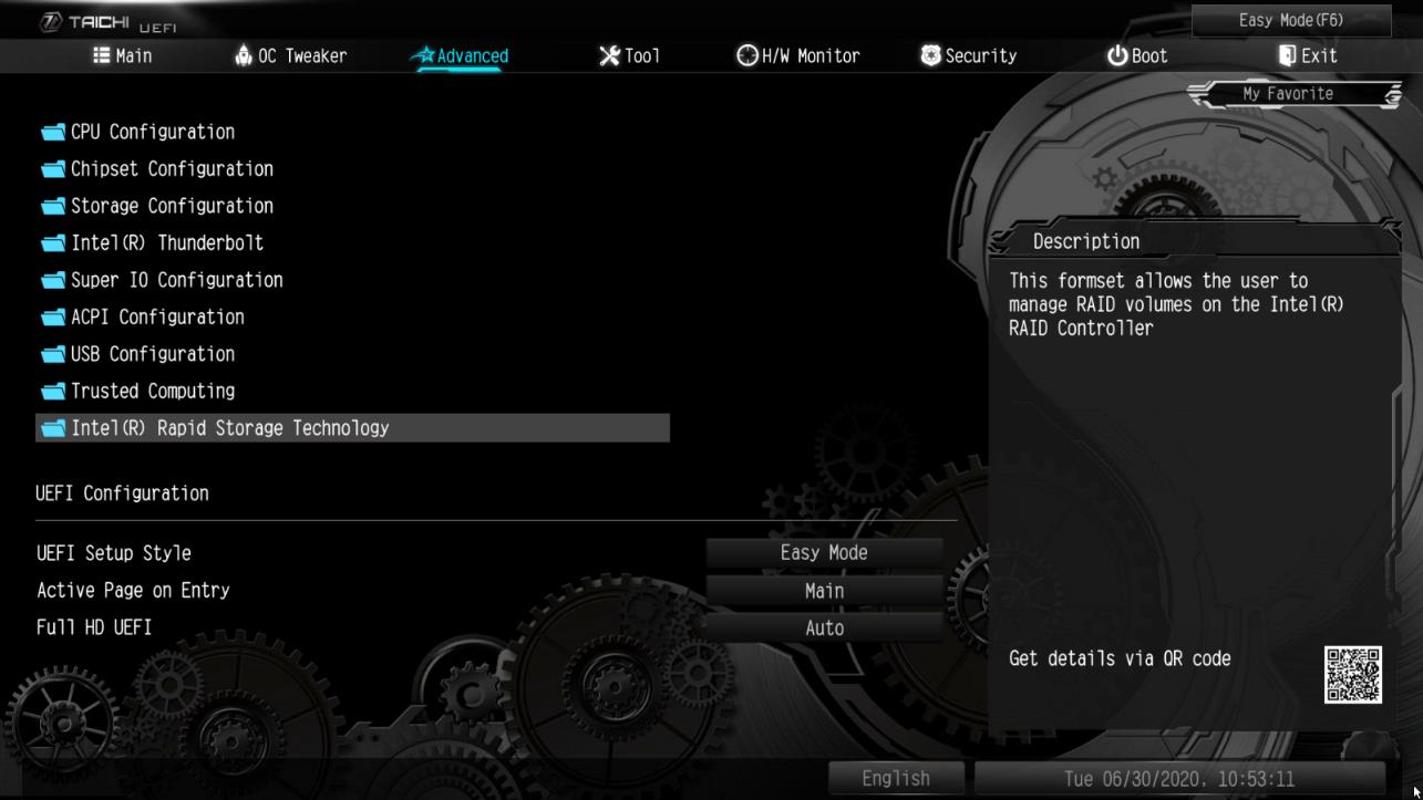
STEP 6. Enter Intel(R) Rapid Storage Technology in Advanced page.
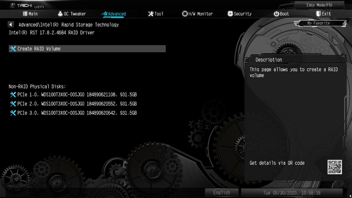
STEP 7. Select the option Create RAID Volume and press .
STEP 8. Key-in a volume name and press , or simply press to accept the default name.
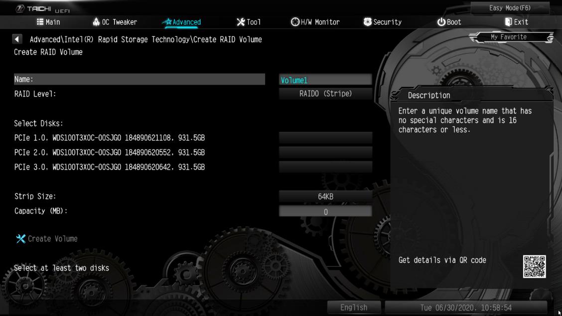
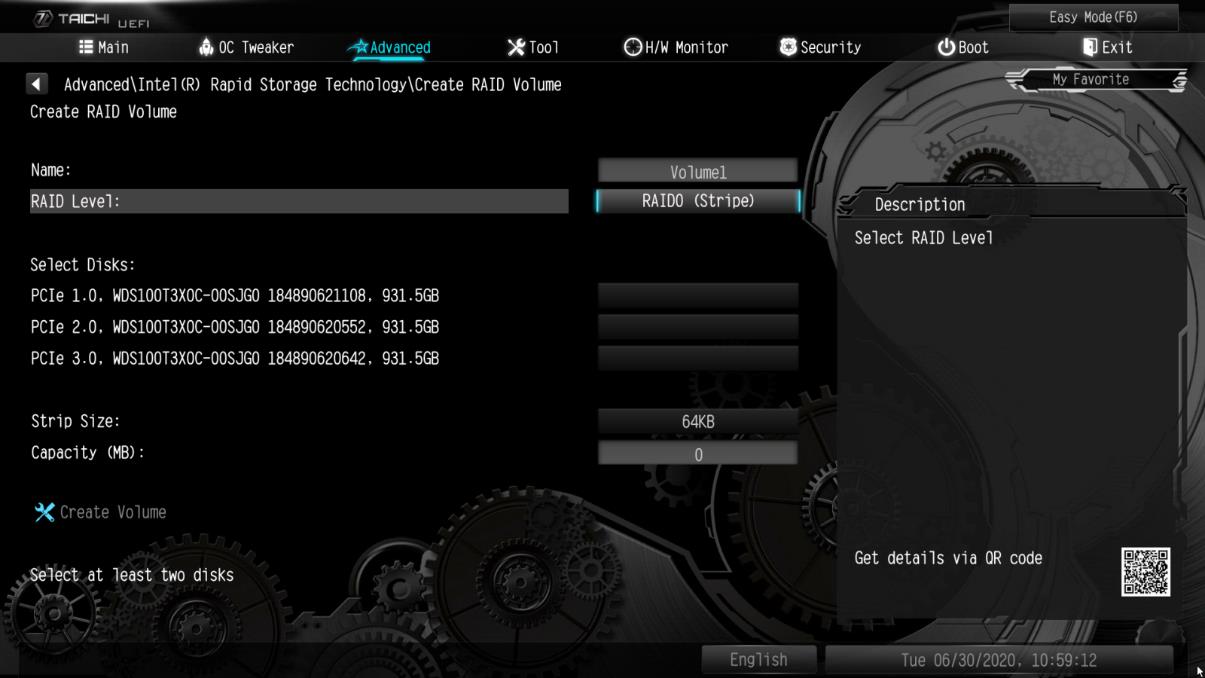
STEP 9. Select your desired RAID Level and press .
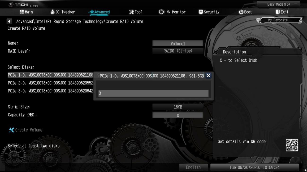
STEP 10. Select the target hard drives which you want to build in RAID array and press .
STEP 11. Select a stripe size for the RAID array and press .
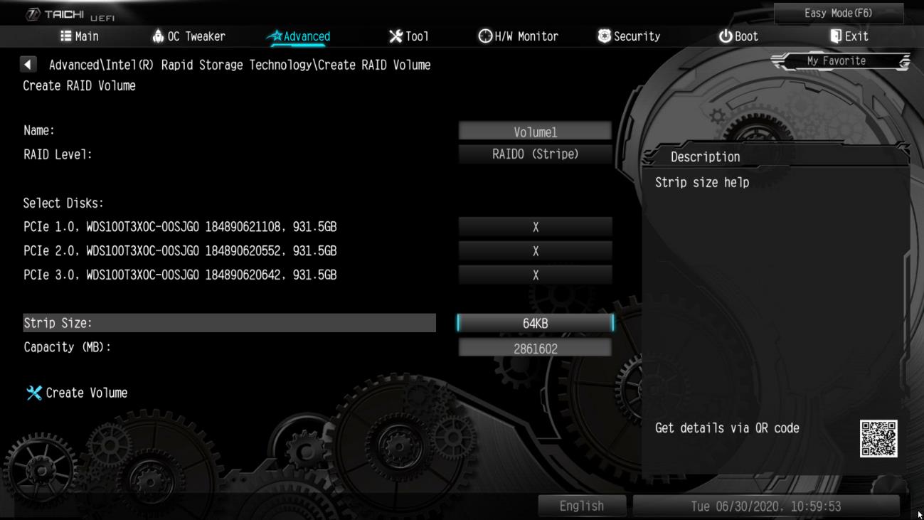
STEP 12. Select Create Volume and press to start creating the RAID array.
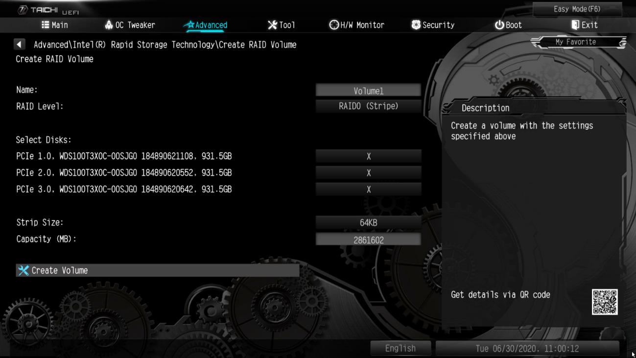
Answer:
If there is a RTK device showing under the device manager and audio port cannot be used, please follow the steps below to remove the RTK device and allow the audio to work properly.
Step 1. Uninstall the Realtek audio driver.
Step 2. Install the Realtek audio driver ver.6.3.9600.2237 from the link below then restart the system.
Link:https://download.asrock.com/Drivers/All/Audio/Realtek_Audio(v6.3.9600.2237).zip
Step 3. Right-click the start icon in the desktop and select the device manager to see if there is RTK Boot showing in your system.
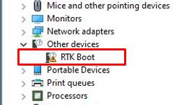
Step 4. Download and extract the Audio Flash Tool from the link below:
Link:https://download.asrock.com/TSD/Desktop/Tool/Audio Flash Tool.zip
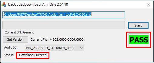
Step 5. Double click the UacCodecDownload_AllInOne_RsProxy_2.64.10
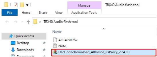
Step 6. Press the Start button to start flashing the audio firmware.
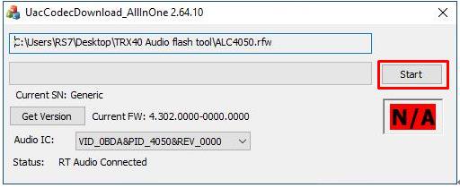
Step 7. Once the flashing process is completed, the tool will show Pass which means audio firmware has successfully flashed and there should not be RTK boot device showing under the device manager.
Answer:
If hissing noise is heard from recordings, please choose one of the methods below to avoid hissing noise.
Method 1:
Step 1.
Download the Realtek high definition audio driver from the ASRock website.
*Please make sure your LAN cable is connected when installing the Realtek audio driver.
Step2:
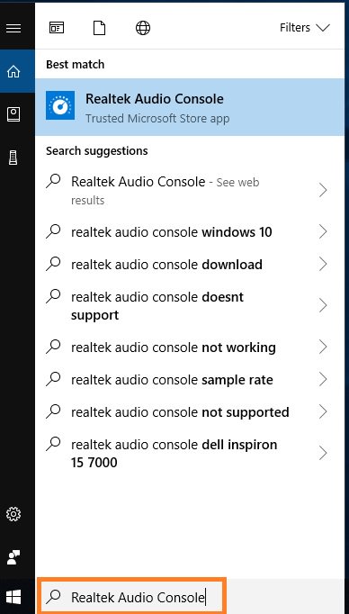
Open the «Realtek audio console”.
Step 3.
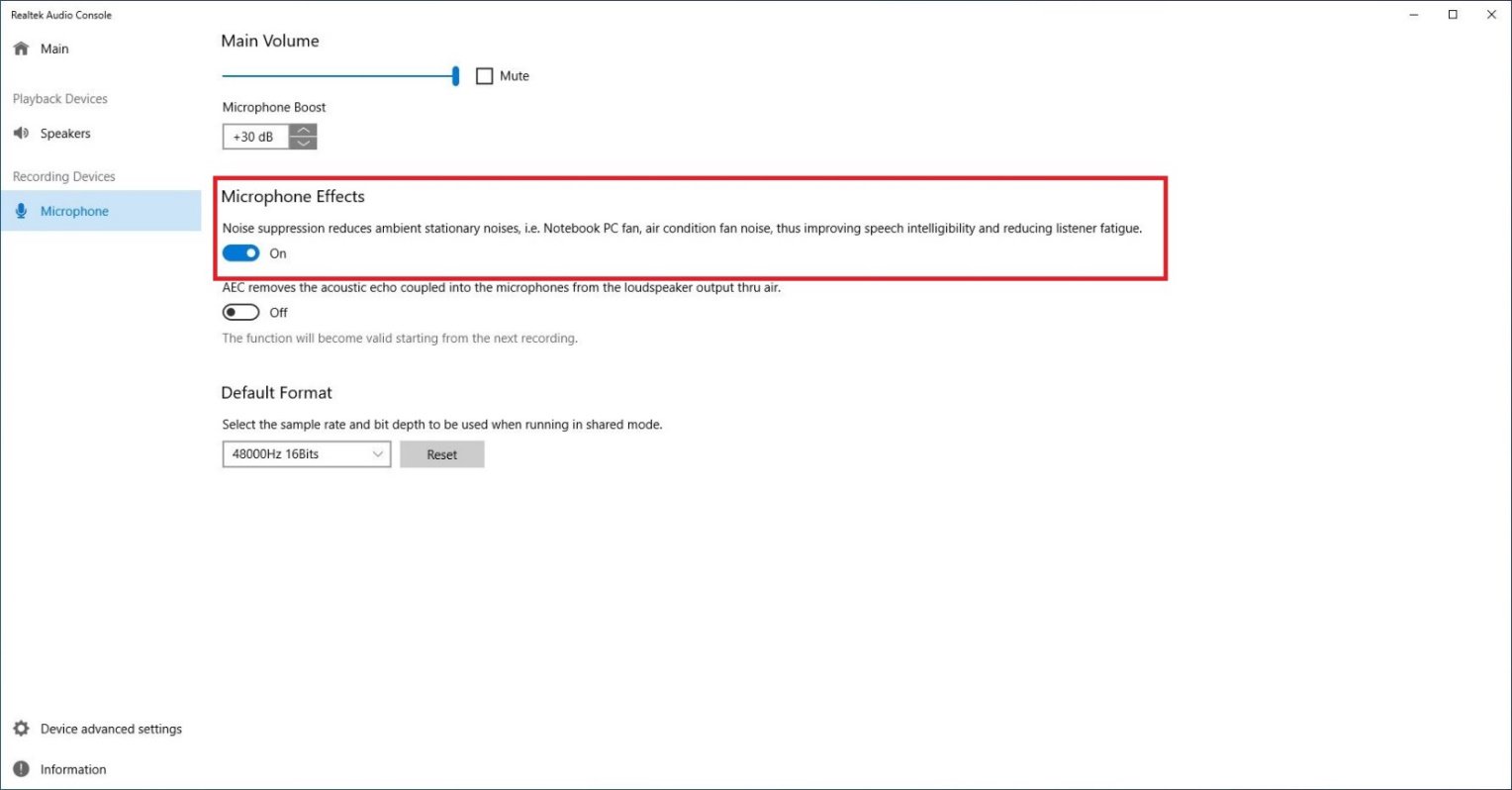
Turn on the «Noise suppression reduces ambient stationary noises” option in the Realtek audio console APP.
Step 4.
Once the setting above is enabled, recording quality will be improved.
Method 2:
Step 1.
Refer to step 1 and step 2 of method 1 to open the «Realtek audio console”.
Step 2.
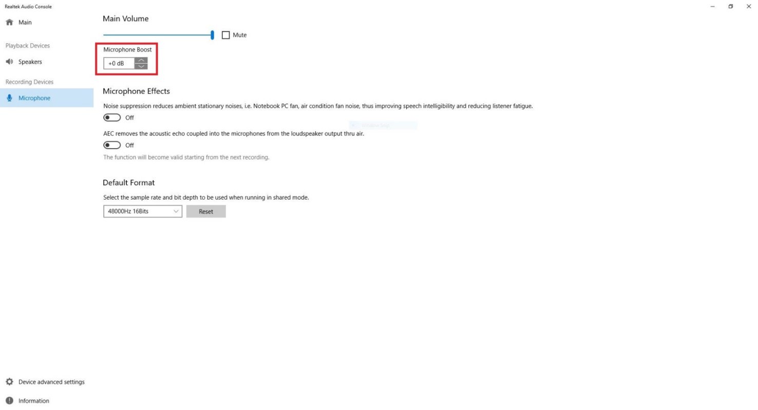
Adjust Microphone Boost to +0db.
Step 3.
Once the boost value is adjusted to +0db, recording quality will be improved.
Answer:
To enable the 4K HDR under Netflix, please follow the steps below:
System Requirements:
Hardware:
— HDR certified monitors
— Dual channel memory
— Picasso or Raven Ridge CPU, which supports HDCP2.2.
— AMD motherboards with DP1.2/HDMI2.0 or higher
Software:
— Win10
— All in One Driver 19.10.28 or later version
— Internet
— Netflix Application
— HEVC Video Extension Application
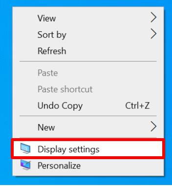
Step 2. Right-click Desktop and select Display settings.
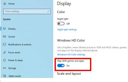
Step 3. Turn on the Play HDR Games and apps.
Step 4. Open the Netflix application and when the word HDR is shown as the following picture, it means that HDR video is ready to be played on Netflix.

Answer:
How to set up Teaming with Intel Ethernet Adapter under Windows10 1809 or later version?
Step1: Access «Device Manager” by searching «Device Manager” at search bar. 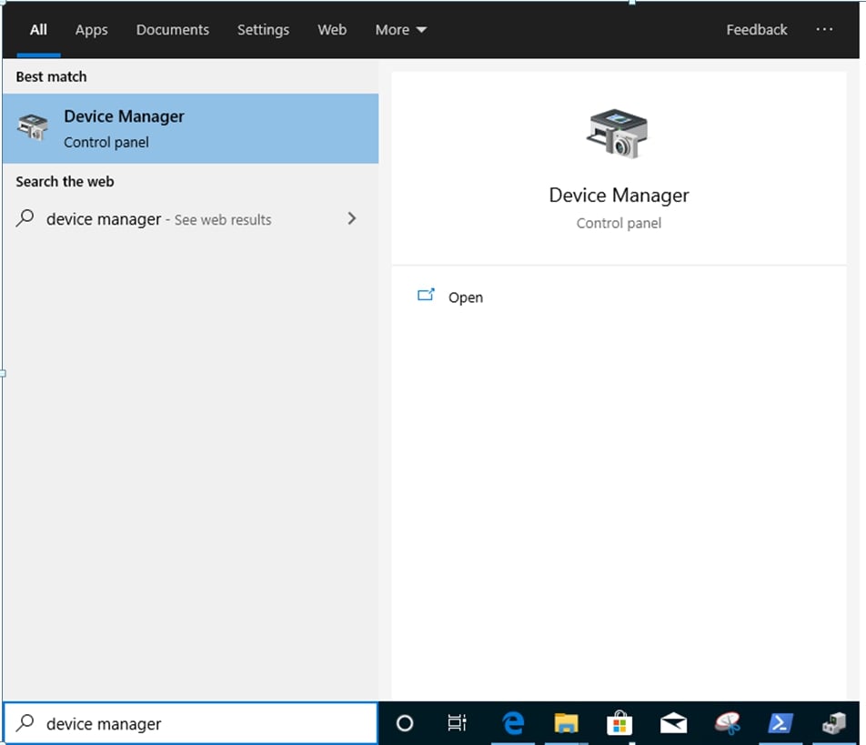
Expand «Network Adapters” and right click the Ethernet device to uninstall it.
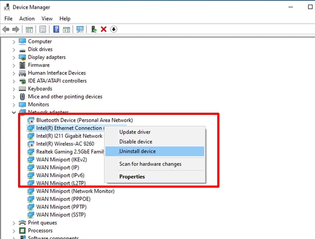
After uninstalling the Ethernet device, please cold boot the system (power off and then back on completely).
Step2: Download the latest driver (later than v23.5) from Intel or ASRock official website for your Intel® Ethernet Adapter.
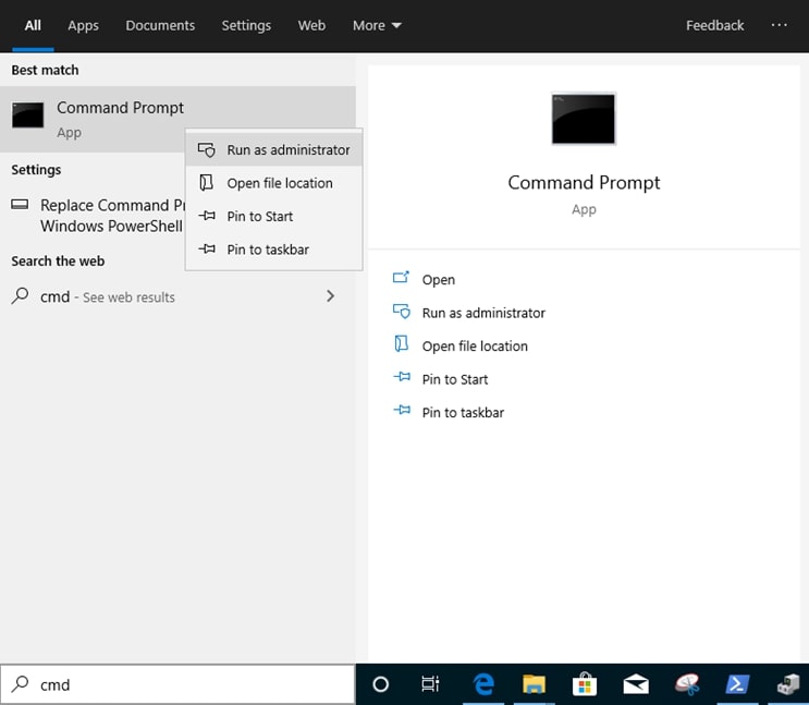
Step3: Search «CMD” at search bar and run Command Prompt as administrator.
Unzip the driver package and go to APPS > PROSETDX > Winx64. Copy the root.

Within the Command prompt, please change the root to APPS > PROSETDX > Winx64 folder by following command:
CD C:\Users\1\Desktop\24_2\APPS\PROSETDX\Winx64.

Step4: Install the driver by entering command:
DxSetup.exe BD=1 PROSET=1 ANS=1 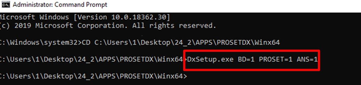
After the driver installation, please reboot the system.
Step5: Search «PowerShell” at search bar and run the Windows PowerShell as administrator
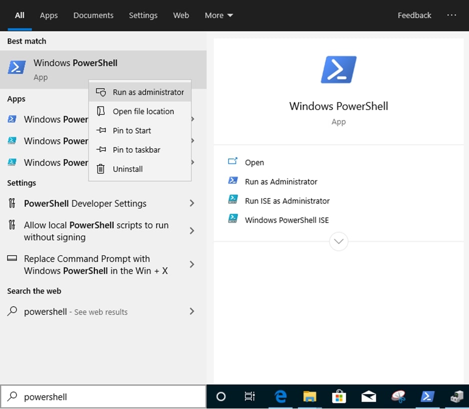
Enter the command:
Import-Module –Name «C:\Program Files\Intel\Wired Networking\IntelNetCmdlets\IntelNetCmdlets.dll»
It would not show any conformation. Please enter another command then:
New-IntelNetTeam 
Step6: The system will ask for your Team Member Names. Please go to «Device Manager» > «Network Adapters» to confirm the names of the Ethernet Adapters. 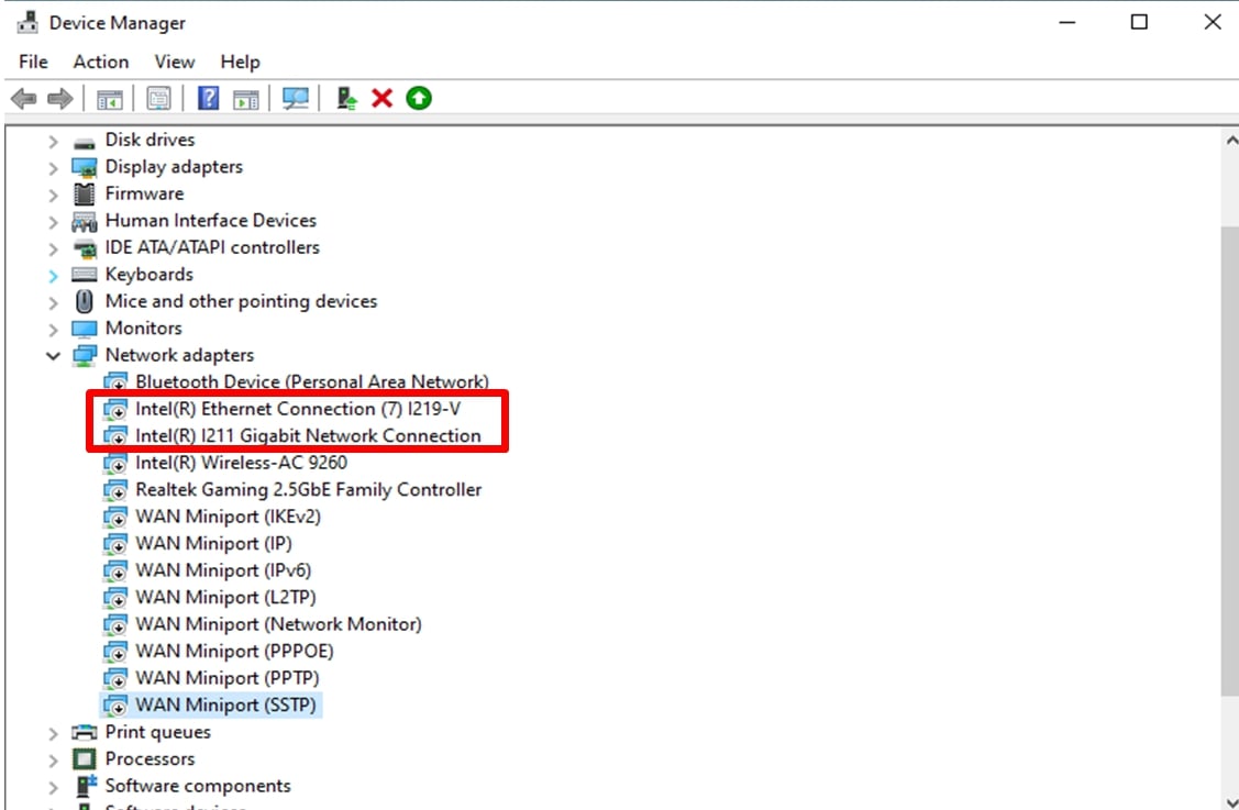
Enter the command:
Inte(R) Ethernet Connection (7) I219-V
Inte(R) I211 Gigabit Network Connection

If you just want to set up a Team by using two Ethernet adapters, please type «Enter” at «TeamMemberName[2]”.
Step7: The system will ask which Team Mode you want. You can refer to the list provided by Intel official website.
https://www.intel.com/content/www/us/en/support/articles/000032008/network-and-io/ethernet-products.html (Here we took the Static Link Aggregation mode for demonstration)
Enter the command:
StaticLinkAggregation

Step8: Enter a friendly Team name:
TEAM0 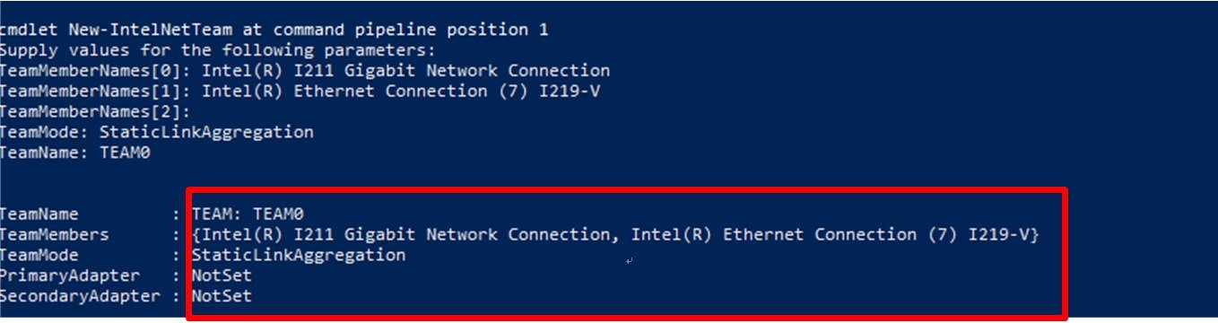
Step9: If you success, find the new Team adapter under Device Manager.
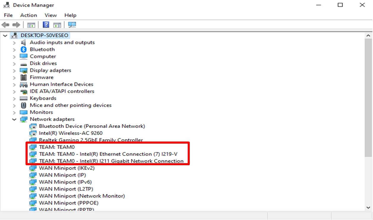
* If you want to uninstall the Team, please use the following command to uninstall it under Powershell:
Remove-IntelNetTeam 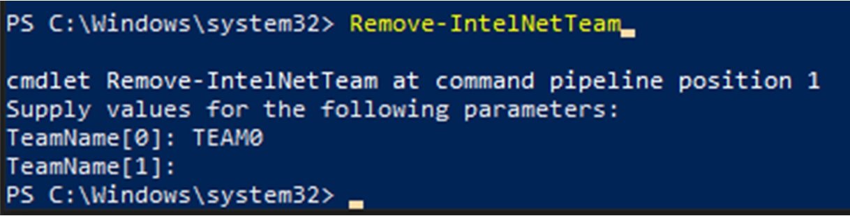
The system will ask you the Team Name, please enter your Team Name and the Team will be uninstalled.
Answer:
Step 1: Please visit ASRock website to download the Intel LAN driver.
https://www.asrock.com/mb/index.asp
Step 2: Refer to the FAQ from the following link to modify the shutdown behavior under Windows 10.
https://www.asrock.com/support/faq.asp?id=408
Step 3: Go to device manager and right click the «Intel® I211/I219 Gigabit Network Connection” LAN device to choose the «Properties”.
Step 4: Intel LAN driver may have two different «Properties”.
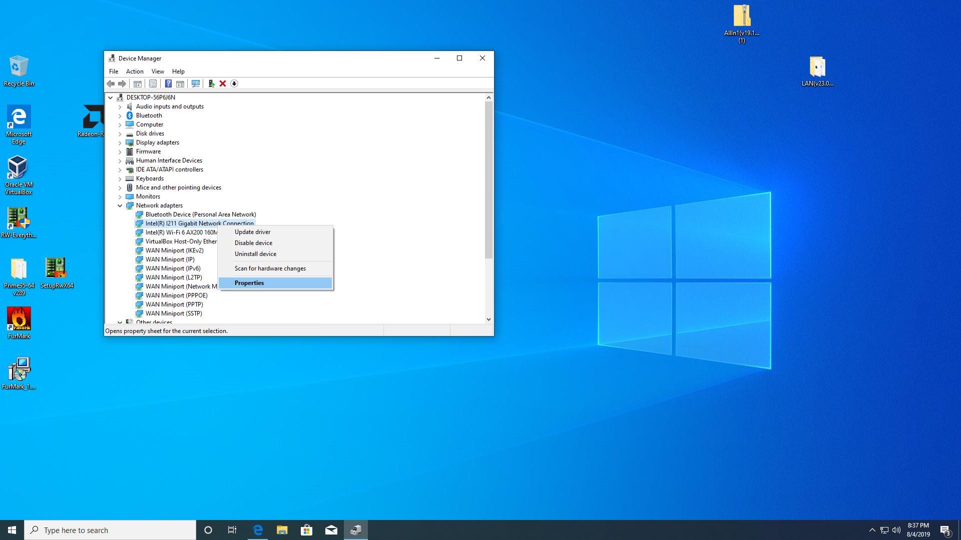
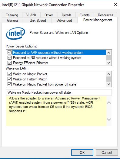
(A) The driver supports «Power saver and Wake on LAN” Option.
Please go to Power management to check all of Wake on LAN function.
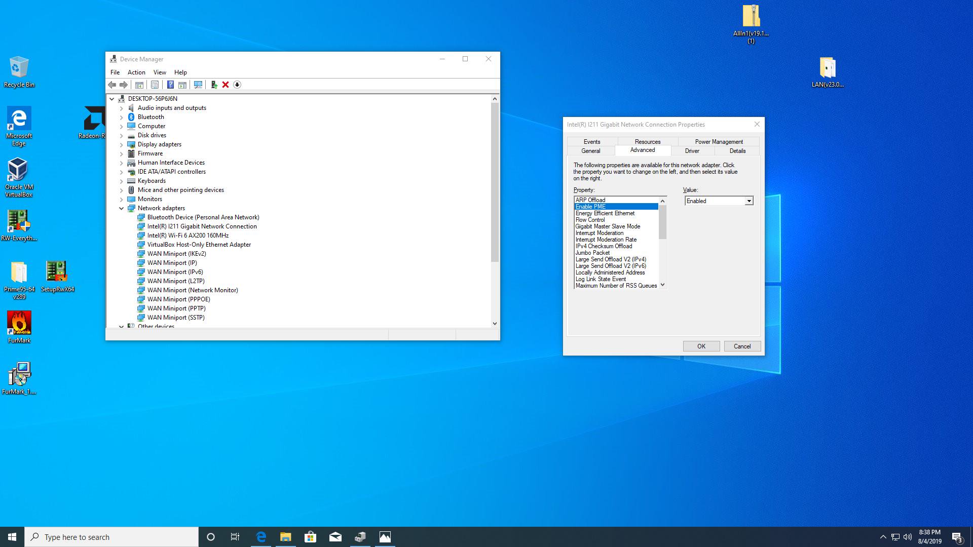
(B) The driver supports «Enabled PME” Option.
Go to «Advanced” and enable the «Enabled PME” option.
Answer:
A new driver may be needed for the following reasons:
1. To support new products or new features
2. To optimize graphics performance or game performance
3. To fix known issues or refine existing features
If your system is working properly, we do not recommend updating the driver.
If you need to update the new driver, you must first uninstall the original driver, restart the computer, and then install the new driver.
Answer:
1. Please download the latest display driver from the official website.
Link: https://www.asrock.com/Graphics-Card/index.asp
2. Make sure your graphics driver version is compatible with the current Operation System.
3. Right click on «Computer” and select «Manage”. 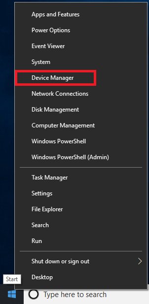
4. Click «Device Manager” and double click «Display adapters”. 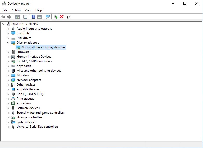
5. Right click on the graphics card and click «Update driver”. 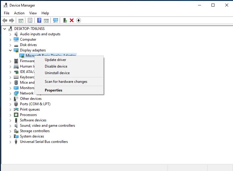
6. Click «Browse my computer for driver software”. 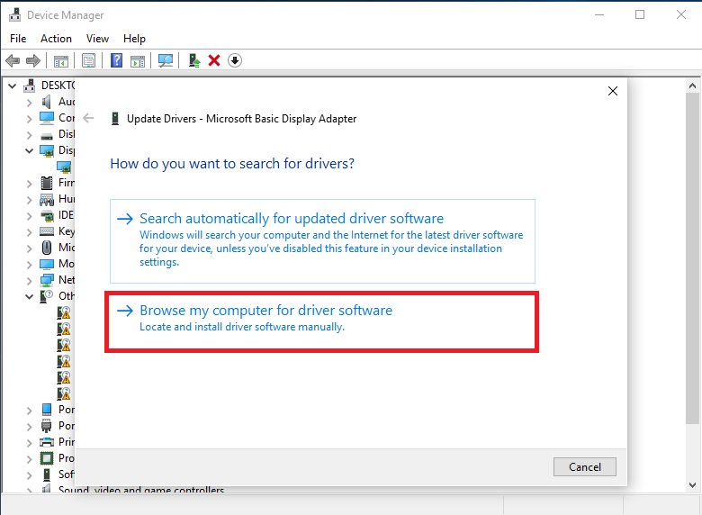
7. Browse for the latest driver downloaded in Step 1. 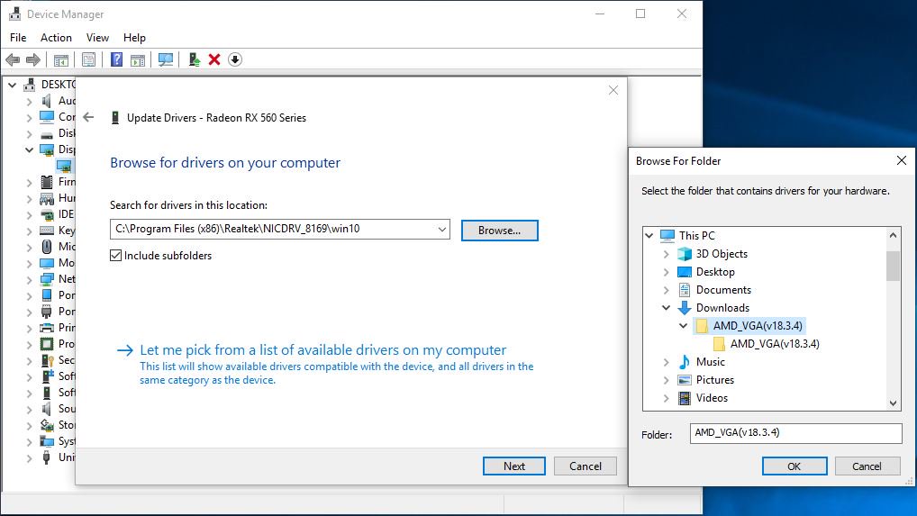
8. Once the driver is installed successfully, you will see the model name of the card.
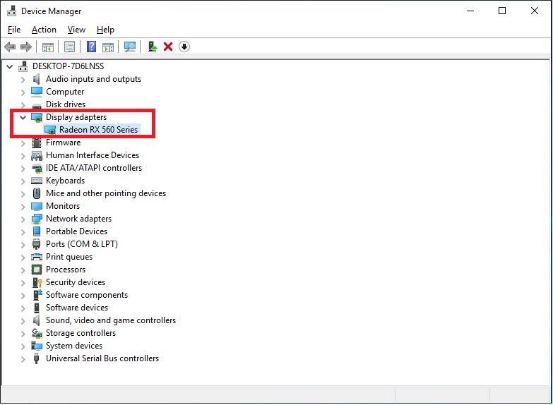
Answer:
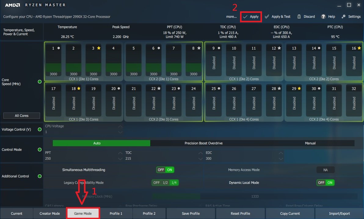
Since some games do not support more than 16 cores, AMD Ryzen Master Utility provides the Game Mode to optimize the graphics performance.
Please refer to below link to download and install the AMD Ryzen Master Utility.
Ryzen Master Download Link: https://www.amd.com/en/technologies/ryzen-master
Follow the steps to select the Game Mode and apply.
After that, graphics performance has been optimized.
Answer:
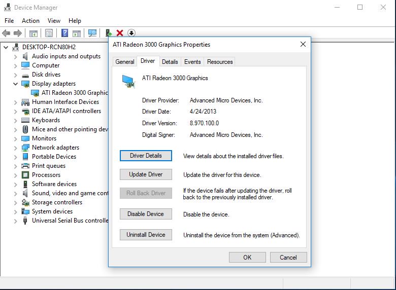
Please refer to the following steps to install the VGA driver manually.
Step 1. Go to the device manager
Step 2. Right click the display adapters to enter the «properties” and choose «Update Driver”.
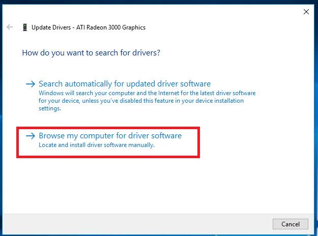
Step 3. Choose «Browse my computer for driver software”.
Step 4. Choose «Let me pick from a list of available drivers on my computer”.
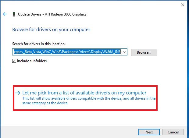
Step 5. Click the «Have Disk” and browse the driver from the disk.
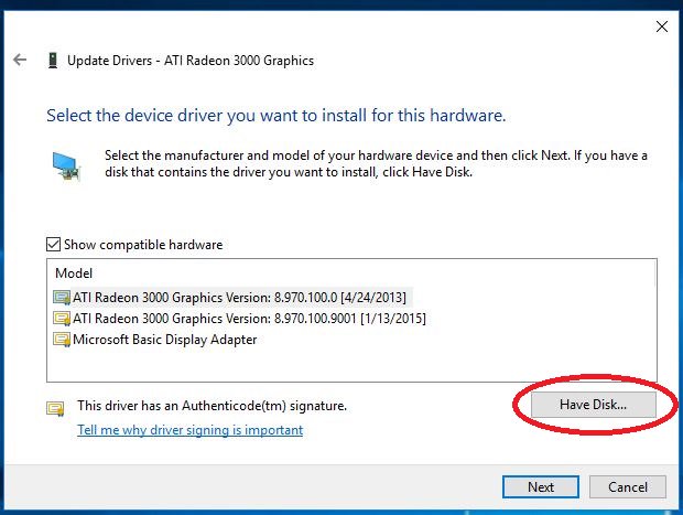
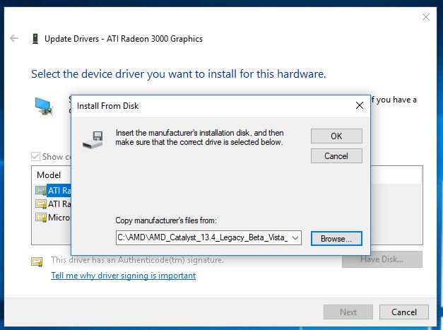
The Path: C:\AMD\AMD_Catalyst_13.4_Legacy_Beta_Vista_Win7_Win8\Packages\Drivers\Dispaly\W86A_INF
Step 6. Click «Ok” and choose «Next” to install driver.
*If the system uses onboard HDMI port to display monitor and the monitor display get the incorrect resolution, please follow the steps below to adjust monitor resolution.
Step 1. Install AMD all in 1 driver as below link:
Link: https://download.asrock.com/Drivers/AMD/AllIn1/Allin1(v15.7.1).zip
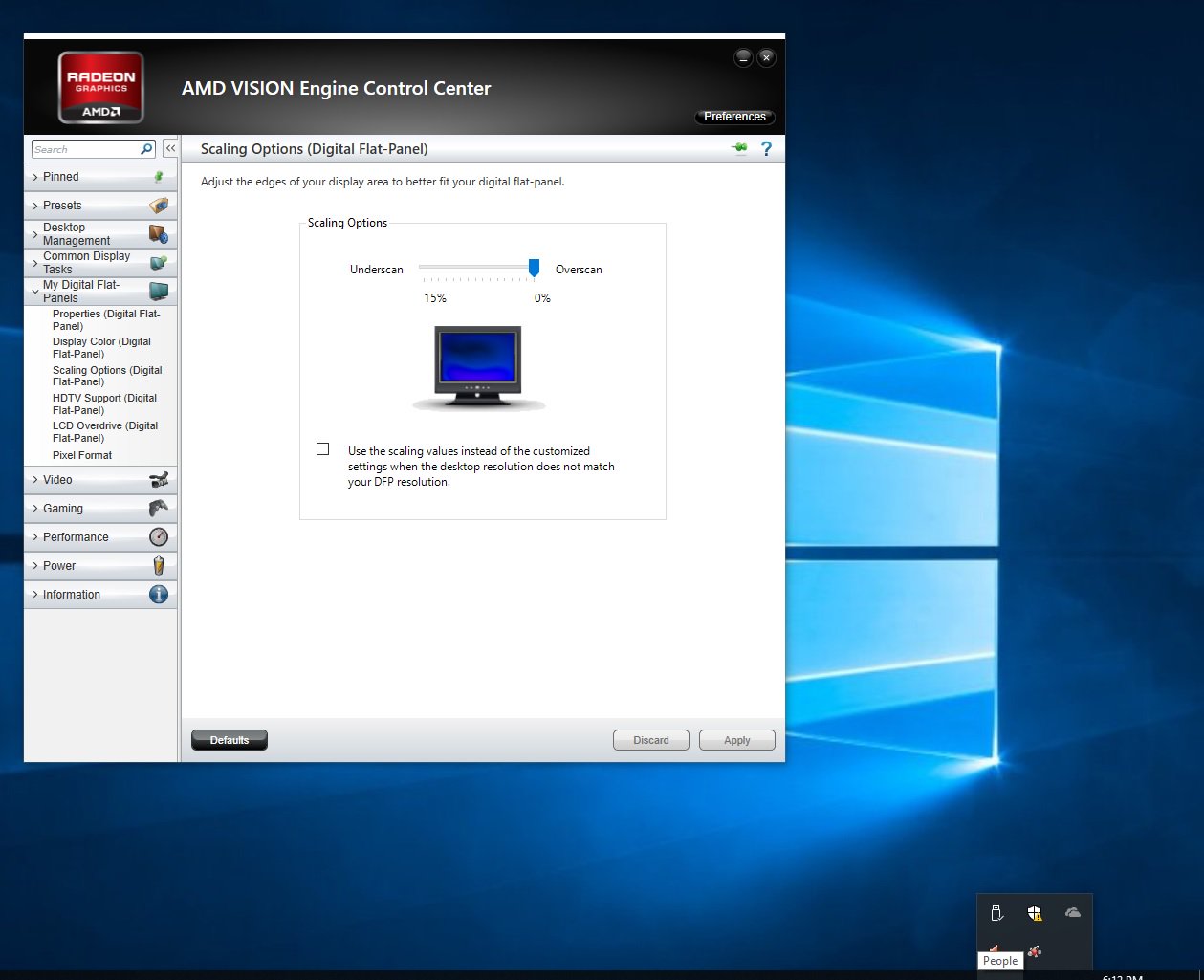
Step 2. Open the «AMD VISION Engine Control Center”.
Step 3. Choose «Scaling Options(Digital Flat-Panel)” and adjust Scaling Options to the Overscan
Answer:
ASRock X399 platform has supported AMD Threadripper 2 CPU since BIOS version P3.XX.
If your BIOS version is older than P3.XX, please update BIOS without powering on the system (without CPU) by using the BIOS Flashback feature that X399 supports.
Please refer to the following procedures to update the BIOS.
1.Visit ASRock website and enter the BIOS download page of your motherboard to download the latest BIOS.
Link: https://www.asrock.com/mb/
2.Copy the BIOS file to your USB flash drive. Please make sure that the file system on the USB flash drive is FAT32.
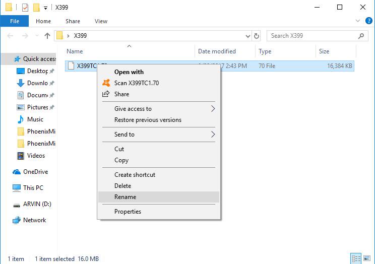
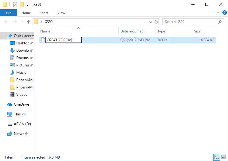
3.Extract BIOS file from the zip file and rename the file to «CREATIVE.ROM”.
4.Plug the 24 pin power connector on the motherboard without other devices. Then turn on the power supply’s AC switch. Please DO NOT power on the system. 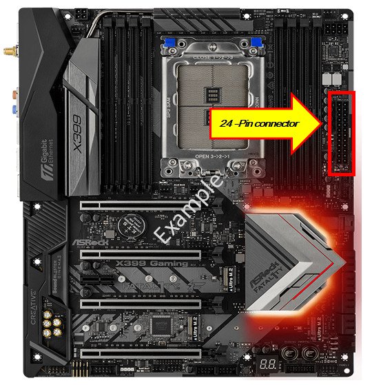
5.Then plug your USB drive to the USB BIOS Flashback port.
*Please refer to the user manual for the detail information of USB Flashback port.
| Model | USB BIOS Flashback port | |
| X399 Taichi | USB3_6 |  |
| X399M Taichi | USB3_6 | 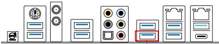 |
| Fatal1ty X399 Professional Gaming | USB3_6 | 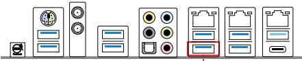 |
6.Press the BIOS Flashback Switch for about three seconds. Then the LED starts to blink. 
7.Wait a few seconds. The BIOS flashing process is completed when the LED stops blinking.
*If the LED light turns solid green, the BIOS Flashback is not operating properly. Please make sure that you plug the USB drive to the USB BIOS Flashback port properly.
Answer:
If you are using the VGA card and onboard display adapter shows an exclamation mark as the picture below,
please follow the steps to remove exclamation mark. 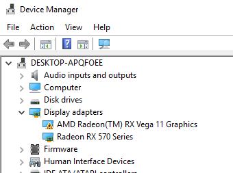
1. Please press «F2” or «Del” during POST to enter BIOS setup
2. Choose primary video adapter as internal graphics
Path: Advanced\AMD PBS\Primary Video Adapter\Int Graphics (IGD) 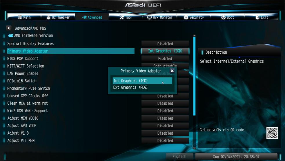
3. After adjusting above options , press «F10” to save the configuration.
You can try below method as well.
1. Please press «F2” or «Del” during POST to enter BIOS setup
2. Disable CSM
Path: Boot/CSM/Disable 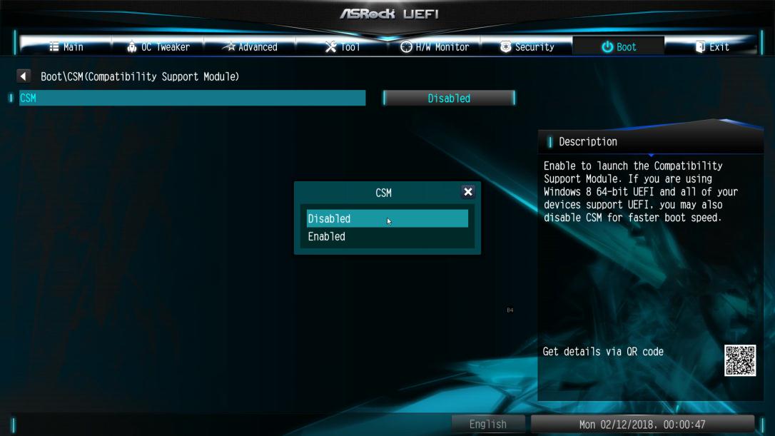
3. After adjusting above option, press «F10” to save the configuration.
Answer:
Please adjust the «UMA Frame buffer Size” under Advanced\North Bridge Configuration:
*To support 4GB shared memory or above, please adjust CSM support to Disable under Boot tab firstly. 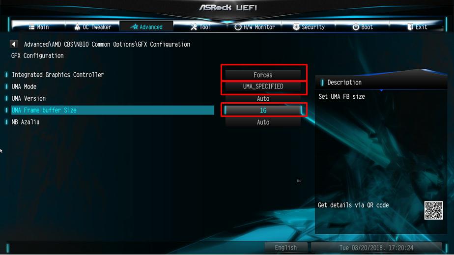
If you don’t see ”UMA Frame buffer Size” under North Bridge Configuration, please follow the steps below to find it and adjust the OC settings.
1. Please press «F2” or «Del” during POST to enter BIOS setup
2. Refer to the following path to adjust the OC setting.
a. Advanced\AMD CBS\NBIO Common Options\GFX Config IGC :Forces
b. Advanced\AMD CBS\NBIO Common Options\UMA Mode : UMA_Spec
c. Advanced\AMD CBS\NBIO Common Options\UMA Frame Buffer Size: Choose a prefer size 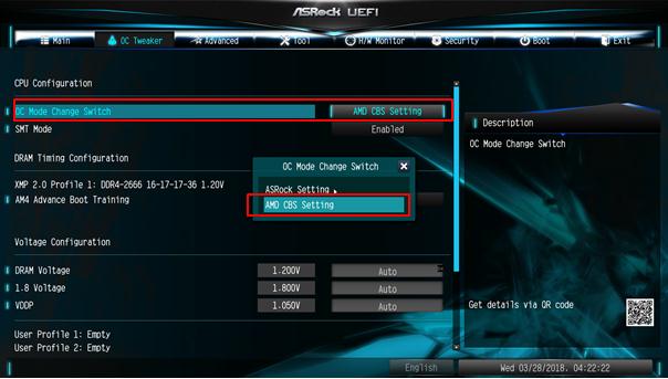
d. OC Tweaker\OC Mode Change Switch\AMD CBS Setting 
3. After adjustment, press «F10” to save the configuration.
Answer:
Please follow below steps to meet your application
Step1: Un-check fast startup option in Control Panel 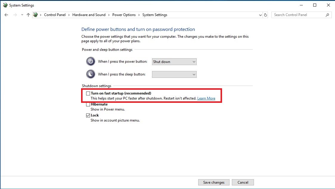
Step2: Unzip EnableWOLInFastStartup file and then right-click Run as administrator WakeOnFastStartup.bat to install it.
Link: https://download.asrock.com/TSD/EnableWOLInFastStartup.zip 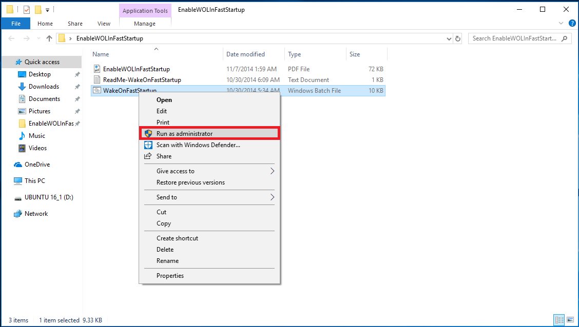
Step3: Check fast startup option in Control Panel. 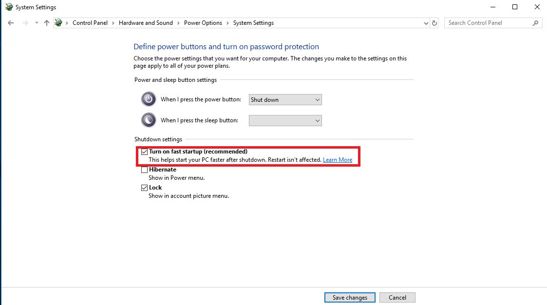
After that, Wake on LAN is enabled in S5 status.
Answer:
If you are having difficulties installing/removing the PCIE devices out, please follow the steps to safely install/remove
the PCIE devices.
Step1: Please shutdown the system and unplug the power cord.
Step2: Find the lock on the PCIE slot 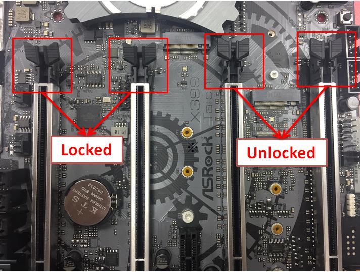
Step3: Please push down the lock gently with one hand to unlock before installing PCIE device 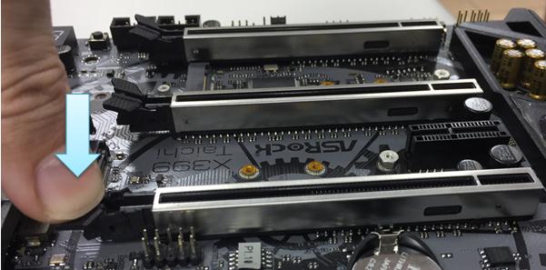
Step4: Plug the PCIE device all the way in with two hands 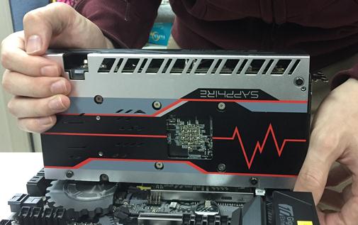
Step5: Please push down the lock gently with one hand to unlock before removes the PCIE device 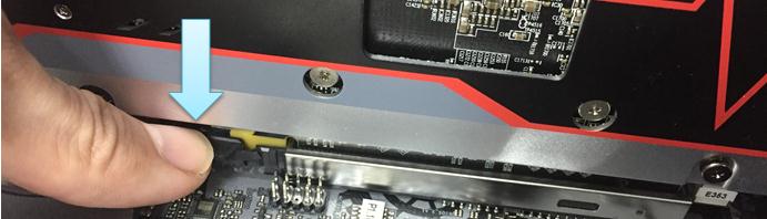
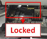
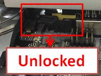
Step6: Remove the card slowly with both hands holding the PCIE devices 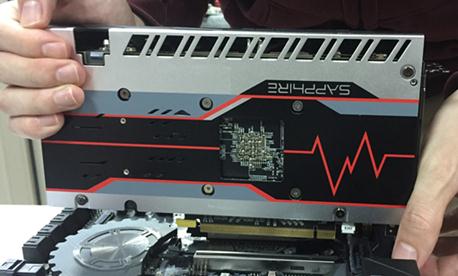
Answer:
If you’ve encountered BSOD and get the error information same as below, please follow the steps to install
AMD all in 1
driver ver:17.40.1025.
[Error information]
Stop code: SYSTEM SERVICE EXCEPTION
What failed: atikmdag.sys 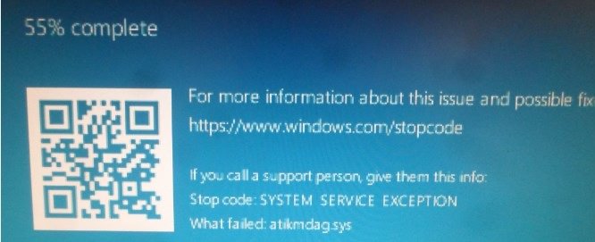
Step1: Please un-install display adapter via Device Manager. 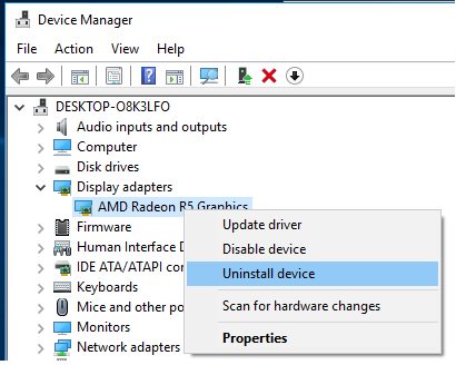
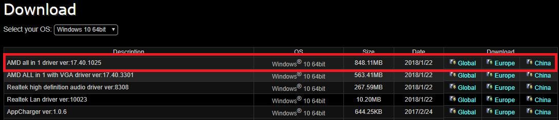
Step2: Download the AMD all in 1 driver ver:17.40.1025 from ASRock website and install it on the system.
Link: https://www.asrock.com/MB/AMD/A320M-HDV/index.asp#Download
Answer:
There are two workarounds to solve the error code «12” issue on the system.
1. Refer to the following link to change the registry under OS.
Link: https://support.microsoft.com/en-us/help/942959/error-message-when-you-attach-a-pci-express-expansion-chassis-to-a-com
Answer:
Please follow the steps below
1. Refer to the «Microsoft Windows Mixed Reality PC hardware guidelines” to check the system hardware requirement.
https://support.microsoft.com/en-us/help/4039260/windows-10-mixed-reality-pc-hardware-guidelines
*The Windows Mixed Reality requires Integrated Intel HD Graphics 620 or greater DX12-capable integrated GPU.
2. If an external graphics card is installed, please enable «IGPU Multi-Monitor” under BIOS.
BIOS Path: Advanced > Chipset Configuration > IGPU Multi-Monitor 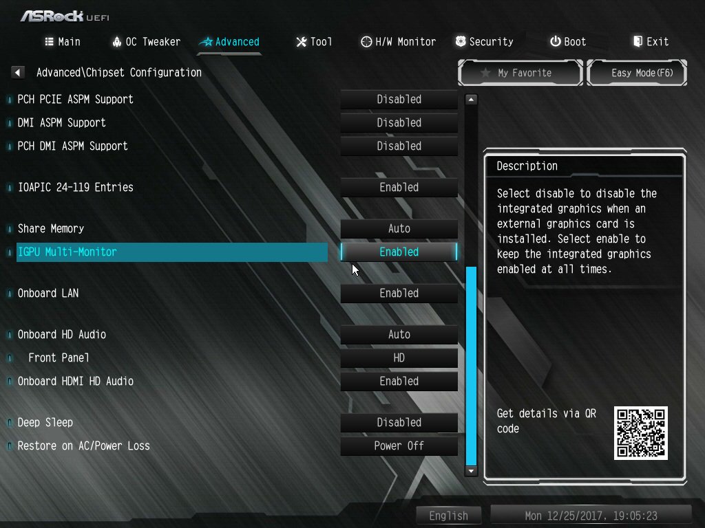
3. Download the VGA driver version 15.60.01.4877 from the Intel download center and Install it on your system.
Download Link: https://downloadcenter.intel.com/product/128199/Graphics-for-8th-Generation-Intel-Processors
4. Install the «Windows Mixed Reality Headset” USB 3.0 connector to the on-board USB3.0 port.
5. Install the «Windows Mixed Reality Headset” HDMI connector to the on-board HDMI port
The Windows Mixed Reality Headset should work now.
Answer:
Yes, it is required to connect the PCIe power connector to PSU.
Please make sure all the connected power connectors are on the same PSU.
| No. | Description |
| 4 | ATX 12V Power Connector (ATX12V1) |
| 7 | ATX Power Connector (ATXPWR1) |
| 18 | PCIe Power Connector (PCIE_PWR2) |
| 24 | PCIe Power Connector (PCIE_PWR1) |

Answer:
Please refer to the following requirements, configurations and setup procedures.
[Requirements]
OS: Windows 10
Receiver / decoder: Onkyo TX-NR 747 or other receiver supporting HDCP 2.2
Player: Pioneer Ultra HD Blu-ray drive
BD Disk: Most 3D / 4K BD disk movie
Playback Software: Power DVD 14 or later version
[Configuration]
M/B: Z270 Gaming-ITX/ac
BIOS: P2.30
[Setup]
1. When the system boots up, press «F2» to enter UEFI setup screen.
Go to Advanced > CPU Configuration and enable «Software Guard Extensions» in BIOS setting.
Press «F10» to save and exit the BIOS setup screen. 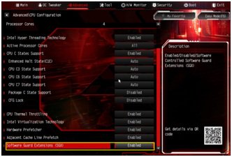
2. Boot into O.S. Install all drivers for the M/B.
Install ME driver ver: 11.6.0.1126 (supports Ultra HD Blu-ray). Download the driver from the following link:
http://www.asrock.com/MB/Intel/Fatal1ty%20Z270%20Gaming-ITXac/index.asp#osW1064
3. Go to Control Panel > Hardware and sound > Sound and select «Receiver output”.
Answer:
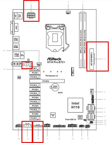
If you have two PSU for your mining system, H110 Pro BTC+ related power connectors must be connected to the same PSU.
Please make sure all the connected power connectors (4-pin, 24-pin, SATA and PCIe) are on the same PSU.
| No. | Description |
| 1 | ATX 12V Power Connector (ATX12V1) |
| 4 | ATX Power Connector (ATXPWR1) |
| 18 | SATA Power Connector (SATA_POW1) |
| 19 | PCIe Power Connector (PCIE_PWR2) |
| 21 | PCIe Power Connector (PCIE_PWR1) |
Answer:
It depends on the complete system configuration. We recommend calculating it in 2 parts:
(1) Motherboard + CPU + memory + SSD:
For a system with an Intel® Pentium® CPU with 2 DIMMs memory, we suggest to reserve 250W for this part.
(2) Graphics cards:
We suggest visiting the official website of the graphics card vendor to check the graphics card TDP. Please refer to the following example.
Nvidia GTX1060: it requires 120W power for each card.
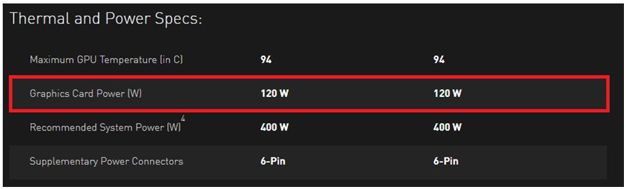
AMD RX470: it requires 120W power for each card.
Link: http://www.amd.com/en-gb/products/graphics/radeon-rx-series/radeon-rx-470 
If the system uses eight RX470 and five GTX1060, the total sum including other components is 1810W. Accounting for power conversion efficiency, the recommended power supply for this example is at least 2400W.
| H110 Pro BTC+ with CPU + memory + SSD | RX470 x Qty | GTX1060 x Qty | Total |
|---|---|---|---|
| 250W | 120W x 8 | 120W x 5 | 1810W |
Answer:
If some graphics cards are not recognized by the system, it is not necessarily related to only the motherboard but also to other components. The riser cards, power supply, graphics cards and even the OS are all key points for the system. Please refer to the following three parts to check your system.
(A) The PCIe riser card
1. Please double check if the graphics cards are installed properly on the riser cards. Or take the graphics cards off the riser cards and install them on the riser cards again.
2. We recommend choosing PCIe riser cards with 6-pin power for the mining system. 
3. If you are using PCIe riser cards with a Molex connector, please use maximum two Molex connectors on each power cable. Not more. 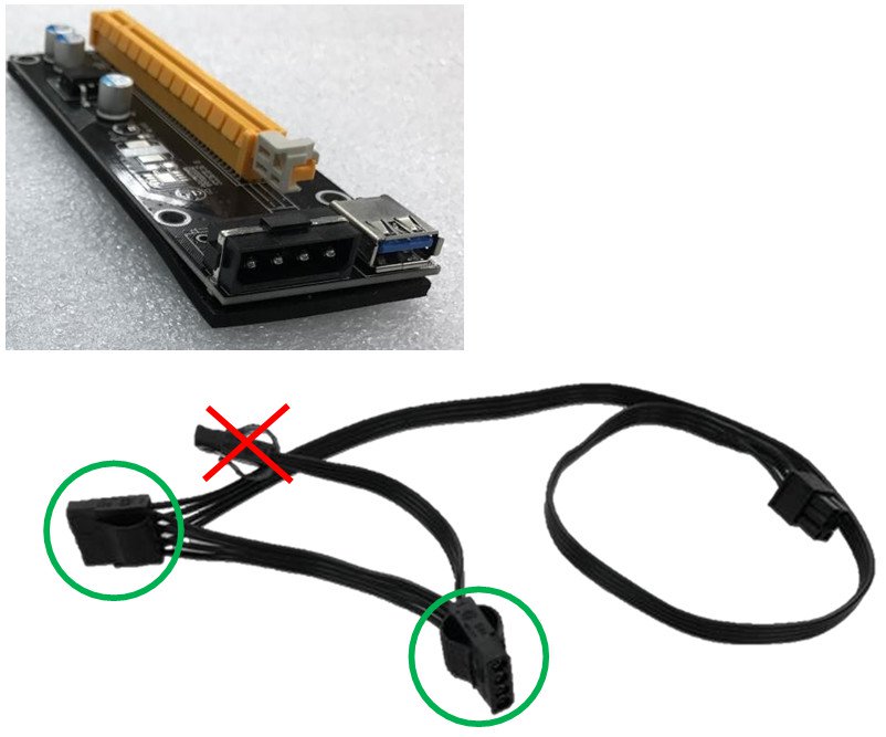
(B) Power supply
When using (close to) 13 graphics cards, you will probably have to use 2 power supplies. Normally the power supply will provide 12V, 5V and 3.3V power to the motherboard.
But in a mining system with multiple power supplies the situation is different. The first power supply has to be connected to the motherboard (12V, 5V and 3.3V) and some of the graphics cards (12V). The second power supply should only be connected to some graphics cards (12V). Because the second power supply will only supply 12V voltage to the graphic cards, it can cause power loading imbalance.
Power supply vendors suggest users to use only one power supply per system.
(C) Graphics cards
1. The single GPU systems typically draw about 200W, the system will need adequate power for whole system. Please double check if the system power is enough for the whole system.
2. Please install one graphics card and make sure it can be recognized under device manager.
If it is not, please shut down the system and press the power button to boot the system again. Then wait for the system to detect the device.
3. If it is not detected please clean the golden finger of the graphics card with a rubber (pencil eraser) and reinstall the card.
Answer:
Step 1. Download the BIOS P1.30 or later version from ASRock’s website
X399 Taichi: https://www.asrock.com/mb/AMD/X399%20Taichi/index.asp#BIOS
X399 Prof. Gaming: https://www.asrock.com/MB/AMD/Fatal1ty%20X399%20Professional%20Gaming/index.asp#BIOS 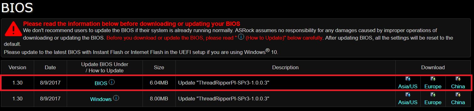
Step 2. Please make sure that the file system of your USB flash drive is FAT32.
Go to This PC → Right click on the mouse → Select Properties → File system 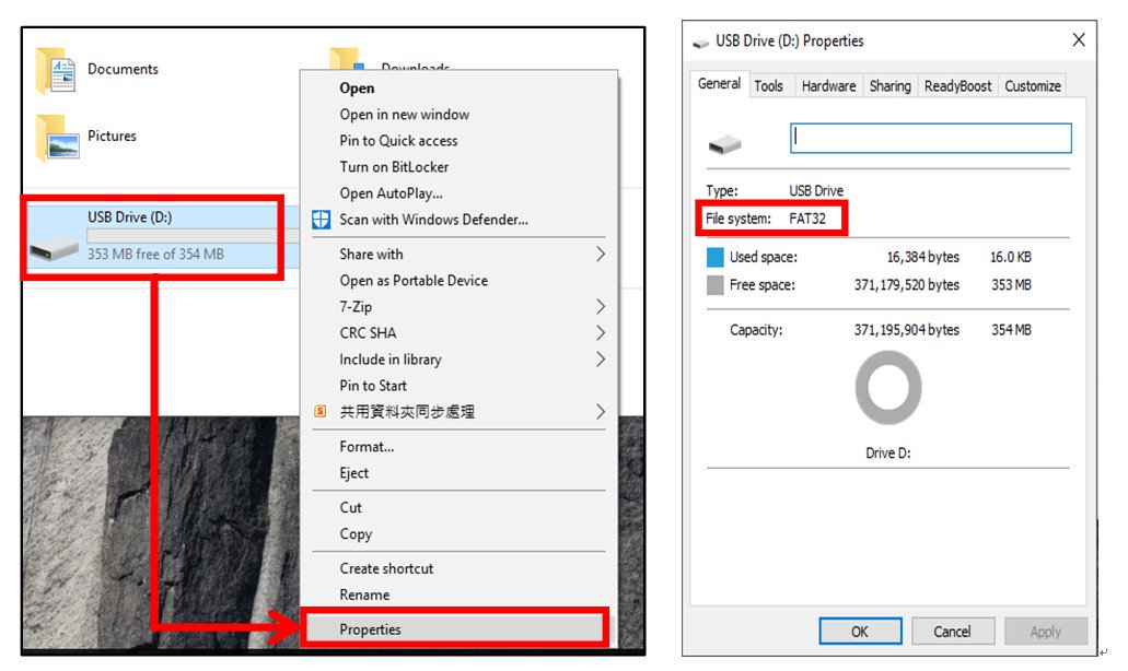
Step 3. If the USB drive is not FAT32 format, please create an USB flash with FAT32 format.
Go to This PC → Right click on the mouse → Select Format → Select FAT32 → Start 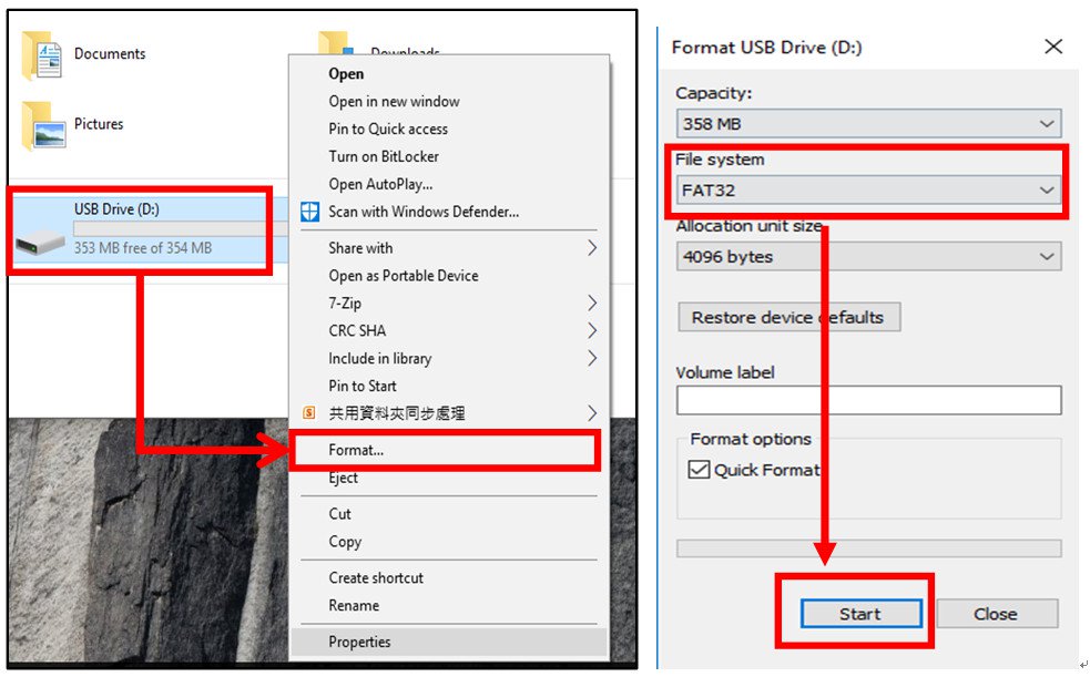
Step 4. Copy the BIOS file to your USB flash drive and extract BIOS file from the zip file. 
Step 5. Rename the file to «creative.rom” and put the file on root directory 
Step 6. Install the 24 pin power connector to the motherboard. Then turn on the AC switch of the power supply.
*There is no need to power on the system. 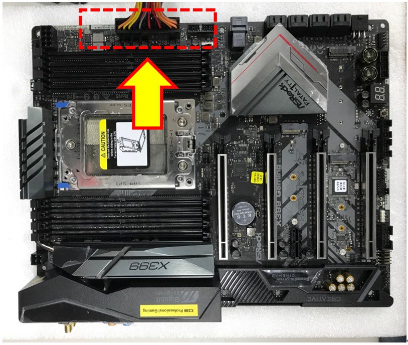
Step 7. Connect your USB drive to the USB BIOS Flashback port. 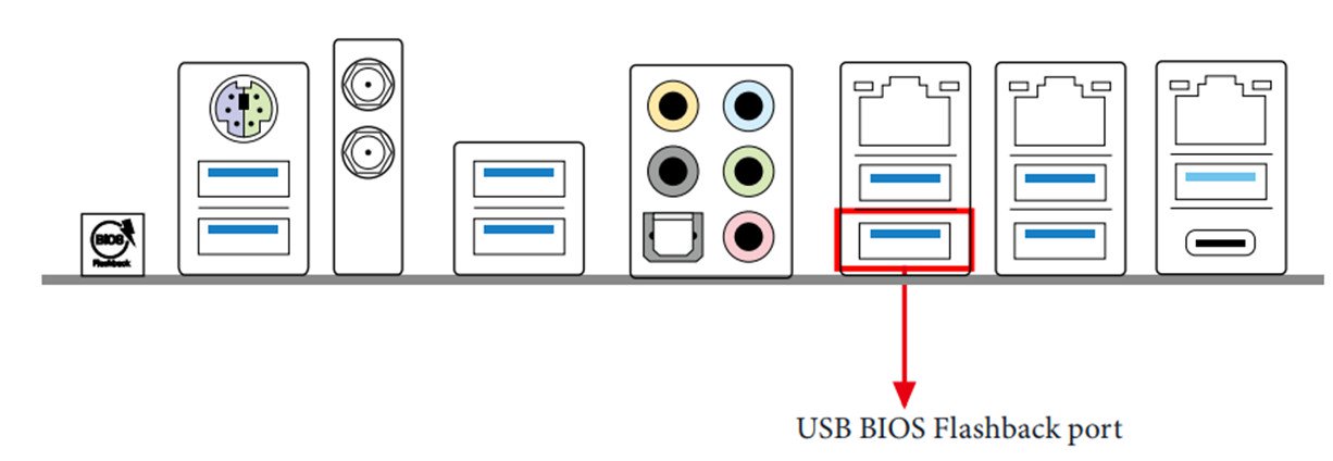
Step 8. Press the BIOS Flashback button for about three seconds. Then the LED starts to blink. 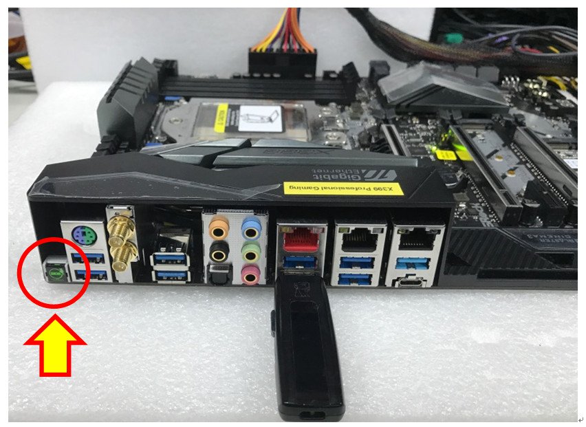
Step 9. Wait until the LED stops blinking, indicating that BIOS flashing has been completed. 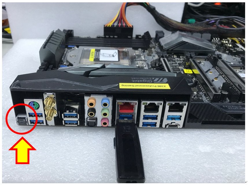
*If the LED light turns solid green, this means that the BIOS Flashback is not operating properly.
1. Please make sure that you connect the USB drive to the USB BIOS Flashback port.
2. BIOS Flashback button (BIOS_FB1, see p.9, No. 19) allows users to flash the BIOS.
3. Flash the BIOS again from step 5.
Answer:
If your motherboard has two PS2 ports, just connect the PS2 mouse to the green PS2 port, and then the PS2 mouse can be used.
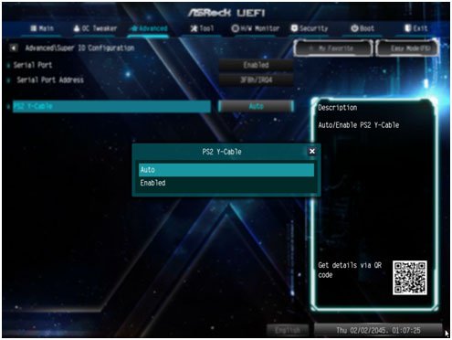
If your motherboard only has one PS2 port, please set «PS2 Y-cable” to «Enabled”. Please press «F2” or «Del” during POST to enter BIOS, select the «Advanced” menu, «Super IO Configuration”, and set the «PS2 Y-cable” option to «Enabled”. Press «F10” to save the configuration. Then the PS2 mouse can be used. 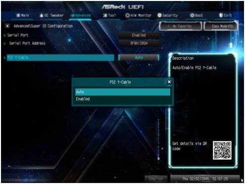
Answer:
USB port power can be turned off by enabling «Deep Sleep” option.
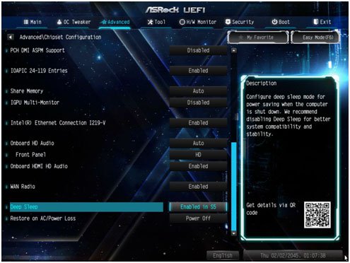
Please press «F2” or «Del” during POST to enter BIOS setup, select the «Advanced” menu and enter the «Chipset Configuration” page, and adjust the «Deep Sleep” option to «Enabled in S5”.
After adjusting the setting, press «F10” to save the configuration. Then USB port power will be turned off under S5 mode. 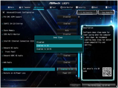
Answer:
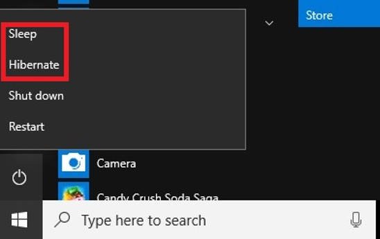
The USB power on function supports under Sleep (S3) and Hibernate (S4) modes under Windows OS.
Please click the Start menu button and then choose Sleep (S3 mode) and Hibernate (S4 mode) under Windows.
Answer:
Requirements:
O/S: Windows 10
Receiver / decoder: Onkyo TX-NR 747 or other receiver supports HDCP 2.2
Playback Software: Power DVD 14 (from Pioneer Ultra HD Blu-ray Drive)
http://www.pioneerelectronics.com/PUSA/Computer/Computer+Drives/BDR-211UBK#overview
Configuration:
M/B: Z170 Gaming-ITX/AC
BIOS: P7.10
CPU: 7th generation Intel® Core™ i7/i5 processor for Desktop PC (Kaby Lake-S)
Setup:
1. Please connect the HDMI cable to HDMI2 port of Z170 Gaming-ITX/ac. 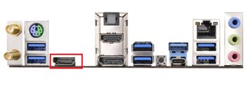
2. When the system boots up, press «F2” to enter UEFI setup screen.
Go to Advanced > CPU Configuration and enable «Software Guard Extensions” in BIOS setting.
Press «F10” to save and exit the BIOS setup screen. 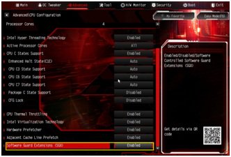
3. Boot into O/S. Install all drivers for the M/B.
Install ME driver(v11.6.0.1126_SW_MSI). Download the driver from the following link:
https://www.asrock.com/MB/Intel/Fatal1ty%20Z270%20Gaming-ITXac/index.asp#osW1064
4. Please enter Control Panel > Hardware and sound > Sound.
Select «HDMI output” 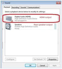
5. Enable the «UHD color” on the TV.
Please run «Ultra Blu-ray advisor” to see if all «Pass”.
Pioneer UHDBD Advisor:
http://pioneer.jp/pcperipherals/bdd/eula.php 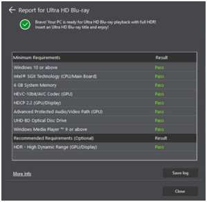
6. Due to the fact that HDR is not supported by Intel 100 series chipset, please disable ”UHD color” from TV.
Put a 4K movie BD disc into the Pioneer Ultra HD Blu-ray drive.
7. Click » Power DVD”.
8. Then you can play the content.
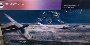
Answer:
Requirements:
O/S: Windows 10
Receiver / decoder: Onkyo TX-NR 747 or other receiver supports HDCP 2.2
Playback Software: Power DVD 14 (from Pioneer Ultra HD Blu-ray Drive)
http://pioneer.jp/pcperipherals/bdd/products/bdr_s11j/spec/
Configuration:
M/B: Z270 Gaming-ITX/ac
BIOS: P1.20
Setup:
1. When the system boots up, press «F2” to enter UEFI setup screen.
Go to Advanced > CPU Configuration and enable «Software Guard Extensions” in BIOS setting.
Press «F10” to save and exit the BIOS setup screen.
2. Boot into O/S. Install all drivers for the M/B.
Install ME driver (v11.6.0.1126_SW_MSI). Download the driver from the following link:
https://www.asrock.com/MB/Intel/Fatal1ty%20Z270%20Gaming-ITXac/index.asp
3. Go to Control Panel > Hardware and sound > Sound and select «HDMI output”.
4. Enable the «UHD color” on the TV.
Please run «Ultra Blu-ray advisor” to see if all «Pass”.
Pioneer UHDBD Advisor:
http://pioneer.jp/pcperipherals/bdd/eula.php 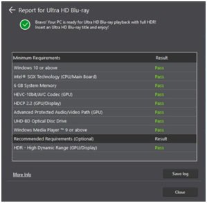
5. Put a 4K movie BD disc into the Pioneer Ultra HD Blu-ray drive.
6. Click «Power DVD”.
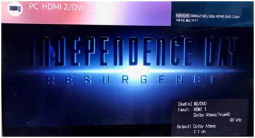
7. Then you can play the content.
Answer:
Error 1— Intel Rapid Storage Technology is Already Installed
→Because your system is already installed Intel Rapid Storage Technology driver, Intel Optane Memory driver cannot be installed properly. Please uninstall Intel Rapid Storage Technology and then install Intel Optane Memory application again. 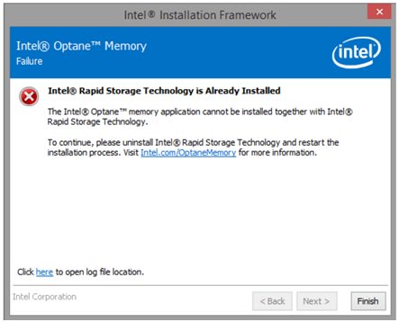
Error 2 — Intel Optane Memory is Currently Enabled
→Before uninstalling Intel Optane Memory application or taking Intel Optane memory to another system,
please must disable Intel Optane Memory acceleration function and then uninstall Intel Optane Memory application or remove Intel Optane Memory from M/B. 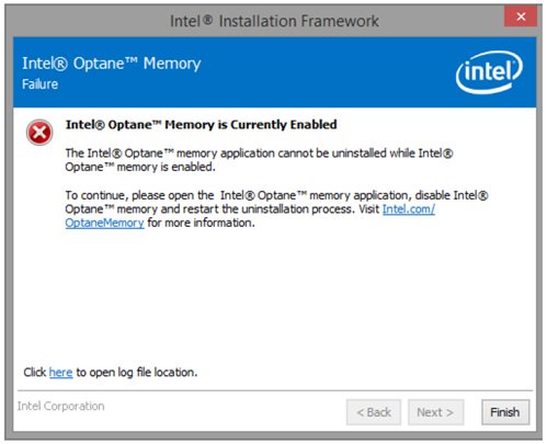
How to disable «Intel Optane Memory Acceleration” function in application?
→Please refer to the following picture to disable the function in Intel Optane Memory application. 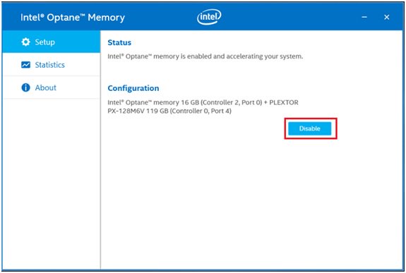
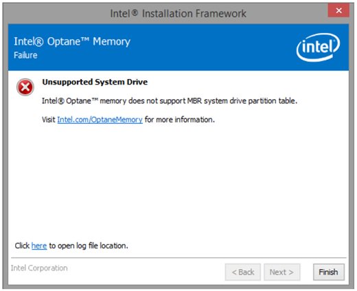
Error 3 — Unsupported System Drive
→Because your system drive is formatted at MBR partition, please re-install your system drive at GPT format.
Answer:
Please refer to the following table for the fan type specification and information.
| Model Name | FAN Header | Which kinds of Cooler type can support Fan speed Control | Control Method | Note |
|---|---|---|---|---|
| Fatal1ty X370 Professional Gaming X370 Taichi |
CPU_OPT/W_PUMP | Both 4-Pin and 3-Pin | Controlled By BIOS setting | Using 3-Pin fan, please set [DC mode] Using 4-Pin fan, please set [PWM mode] |
| CPU_FAN1 | Both 4-Pin and 3-Pin | Auto detect* | System will auto detect the fan type | |
| CHA_FAN1 | Both 4-Pin and 3-Pin | Auto detect* | System will auto detect the fan type | |
| CHA_FAN2 | Both 4-Pin and 3-Pin | Auto detect* | System will auto detect the fan type | |
| CHA_FAN3/W_PUMP | Both 4-Pin and 3-Pin | Controlled By BIOS setting | Using 3-Pin fan, please set [DC mode] Using 4-Pin fan, please set [PWM mode] |
|
| X370 Killer SLI/ac X370 Killer SLI Fatal1ty X370 Gaming K4 |
CPU_OPT/W_PUMP | Both 4-Pin and 3-Pin | Controlled By BIOS setting | Using 3-Pin fan, please set [DC mode] Using 4-Pin fan, please set [PWM mode] |
| CPU_FAN1 | Only 4 Pin | When using 3-Pin fan, it works at full speed | ||
| CHA_FAN1 | Only 4 Pin | When using 3-Pin fan, it works at full speed | ||
| CHA_FAN2 | Both 4-Pin and 3-Pin | Auto detect* | System will auto detect the fan type | |
| CHA_FAN3/W_PUMP | Both 4-Pin and 3-Pin | Controlled By BIOS setting | Using 3-Pin fan, please set [DC mode] Using 4-Pin fan, please set [PWM mode] |
|
| Fatal1ty AB350 Gaming K4 AB350 Pro4 |
CPU_FAN1 | Only 4 Pin | When using 3-Pin fan, it works at full speed | |
| CHA_FAN1 | Only 4 Pin | When using 3-Pin fan, it works at full speed | ||
| CHA_FAN2 | Both 4-Pin and 3-Pin | Auto detect* | System will auto detect the fan type | |
| CHA_FAN3 | Both 4-Pin and 3-Pin | Auto detect* | System will auto detect the fan type | |
| AB350M Pro4 A320M Pro4 |
CPU_FAN1 | Only 4 Pin | When using 3-Pin fan, it works at full speed | |
| CHA_FAN1 | Both 4-Pin and 3-Pin | Auto detect* | System will auto detect the fan type | |
| CHA_FAN2 | Doesn’t support fan control | |||
| AB350M-HDV AB350M A320M-HDV A320M A320M-DGS |
CPU_FAN1 | Only 4 Pin | When using 3-Pin fan, it works at full speed | |
| CHA_FAN1 | Only 4 Pin | When using 3-Pin fan, it works at full speed | ||
| CHA_FAN2 | Doesn’t support fan control |
*Auto detect – system will automatically detect the fan type installed, so user doesn’t set «DC or PWM» mode additionally under BIOS setup.
Answer:
Since AMD AM4 is a new structure and we just found BIOS cannot be completely updated by our Instant Flash. Thus, for the old BIOS version released before 2017/03/07, there is no «Instant Flash” option under BIOS. To make sure BIOS update can be executed completely, please use DOS or Windows BIOS update methods to do update temporarily.
After updating to the following version, Instant Flash functions and options are supported under BIOS and it can be used for updating the newer BIOS file in the future.
| Model | BIOS Version |
|---|---|
| Fatal1ty X370 Professional Gaming | P1.50 |
| X370 Taichi | P1.50 |
| X370 Killer SLI/ac | P1.60 |
| X370 Killer SLI | P1.60 |
| Fatal1ty X370 Gaming K4 | P1.60 |
| Fatal1ty AB350 Gaming K4 | P1.40 |
| AB350 Pro4 | P1.40 |
| AB350M | P1.20 |
Answer:
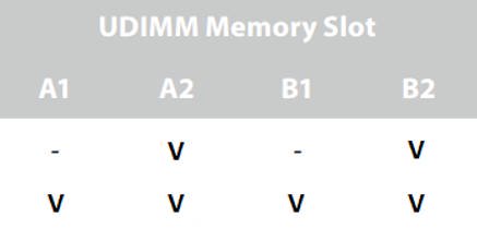
If you install only two memory modules, please install DIMMs into DDR4_A2 and DDR4_B2 slots.
If DDR4_A2 and DDR4_B2 are occupied, please install the other memory modules to DDR4_A1 and DDR4_B1
Answer:
If you have a TPM module on the motherboard and want to update BIOS, please follow the steps below to disable TPM function before flashing BIOS.
In OS:
1. Right-click the Menu button.
2. Left-click > Control Panel > System and Security > BitLocker Drive Encryption
3. Turn off BitLocker 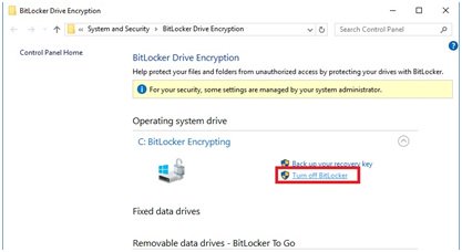
In BIOS
1. BIOS setup > Advanced > Trusted Computing
2. Security Device Support to «Disable” 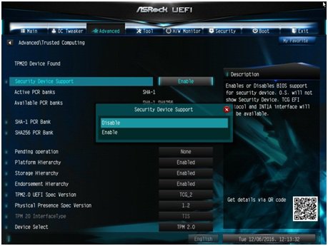
After flashing the BIOS, please enable the function.
Answer:
Please follow below steps to update the ASM1074 firmware:
※This FW Update Tool can only be used on Intel Braswell platform, with Windows 7 64bit / Windows 10 64bit.
Press here to download FW Update Tool
1. Run the tool as Administrator. 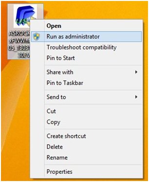
2. Please make sure there’s no device connected to the ASM1074 hub, and then press «Yes” to execute updating. 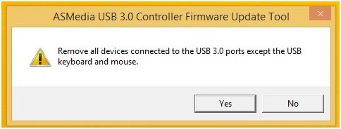
3. The F/W update is processing. 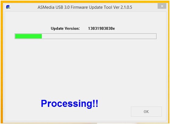
4. After the process finished, please restart the system.
5. Please shut down the system, and unplug the AC power cord for 3 minutes.
6. The firmware update process is finished.
※If the update process tool stops during updating as below, do the followings. 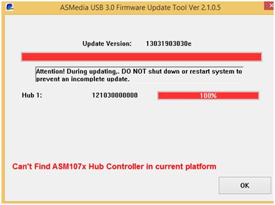
1. Please press «OK” and follow the message to restart the system and then try again.
You will see a message as below: 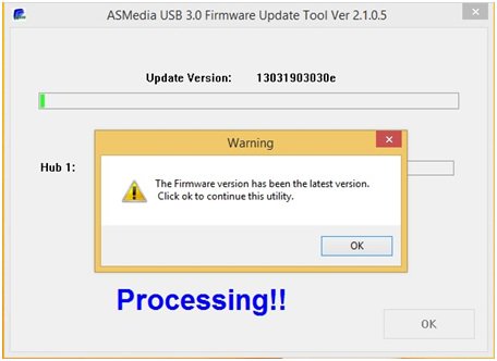
2. Please press «OK”, the system will start to update the firmware again.
(It’s normal that the «update version” is 13031903030e) 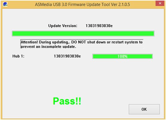
3. After it’s finished, please restart the system.
4. Please shut down the system, and then unplug the AC power cord for 3 minutes.
5. The firmware updating process is finished.
Answer:
1. Please open the chassis and you can find a white sticker at the edge of board with 12-digit MAC ID. 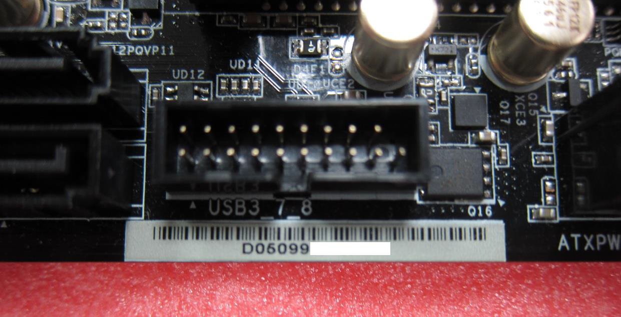
3. Extract (Unzip) the file as «MAC161B”folder then put entire folder into a bootable USB flash drive root directory.
4. Boot up system than press [F11]to enter the Boot Menu, select your USB Flash, afterwards. 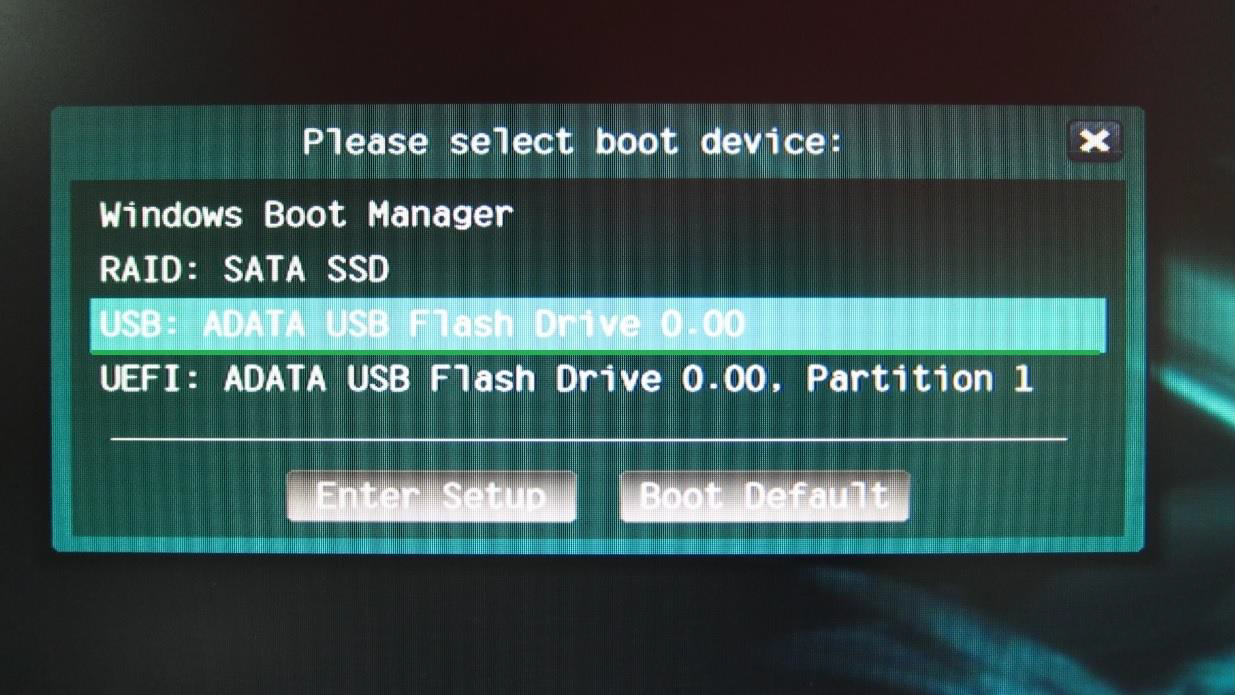
5. Under DOS environment, please key in the command as follow:
Cd MAC161B
(XXXXXXXXXXXXis MAC Address;please refer to the step1 to check the MAC Sticker) 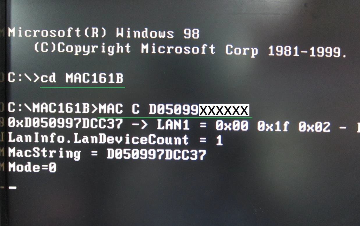
6. After Key in the instruction, the system will flash MAC address automatically.
7. When «Done» showing, the MAC address already been flash successfully.
You can reboot the system into OS.
Answer:
To support the Intel Broadwell-E CPU, please refer to the following table and update your BIOS version.
Download Link: https://www.asrock.com/support/index.asp
| Model | BIOS Version |
| X99 Extreme11 | P3.00 |
| X99 Extreme6 | P3.00 |
| X99 Extreme6/3.1 | P3.00 |
| X99 Extreme4 | P3.30 |
| X99 Extreme4/3.1 | P3.00 |
| X99 Extreme3 | P3.30 |
| X99 OC Formula | P3.00 |
| X99 OC Formula/3.1 | P3.20 |
| X99 Professional | P3.10 |
| X99 Professional/3.1 | P3.20 |
| X99E-ITX/ac | P3.10 |
| X99M Killer | P3.00 |
| X99M Killer/3.1 | P3.30 |
| X99X Killer | P3.00 |
| X99X Killer/3.1 | P3.00 |
| X99 WS-E/10G | P3.00 |
| X99 WS-E | P3.00 |
| X99 WS | P3.10 |
Answer:
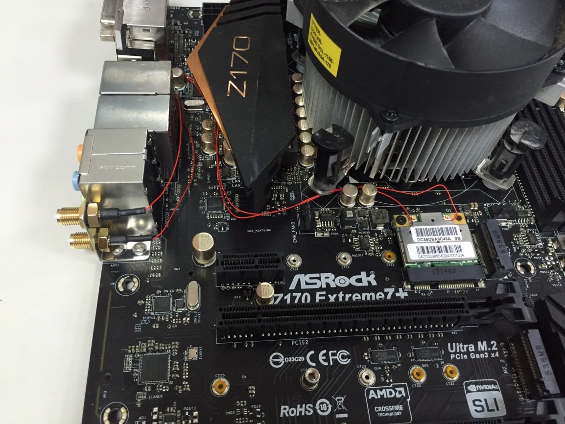
If the connection wires between WiFi antennas and mini-PCIe WiFi card are less than 26 cm, please refer to the following steps.
Step 1. Loosen the five screws marked in yellow circles on the back side of Z170 Extreme 7+. Then remove the I/O cover. 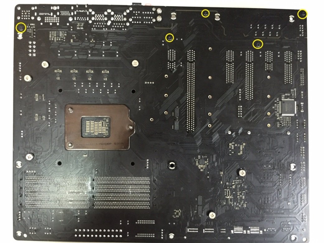
Step 2. Use the red wires to connect the mini-PCIe WiFi card to WiFi antenna ports on the I/O port. 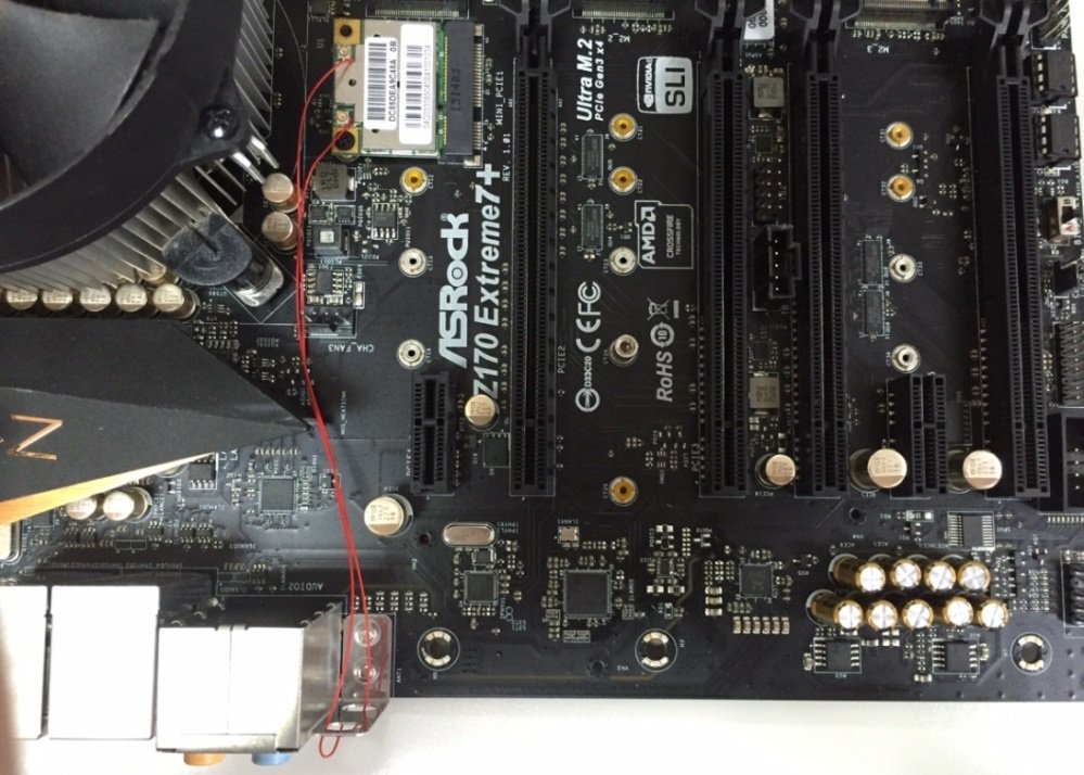
If the connection wires between WiFi antennas and mini-PCIe WiFi card are longer than 26 cm, please follow the steps below.
Step 1 –Loosen the five screws marked in yellow circles on the back side of Z170 Extreme 7+. Then remove the IO cover. 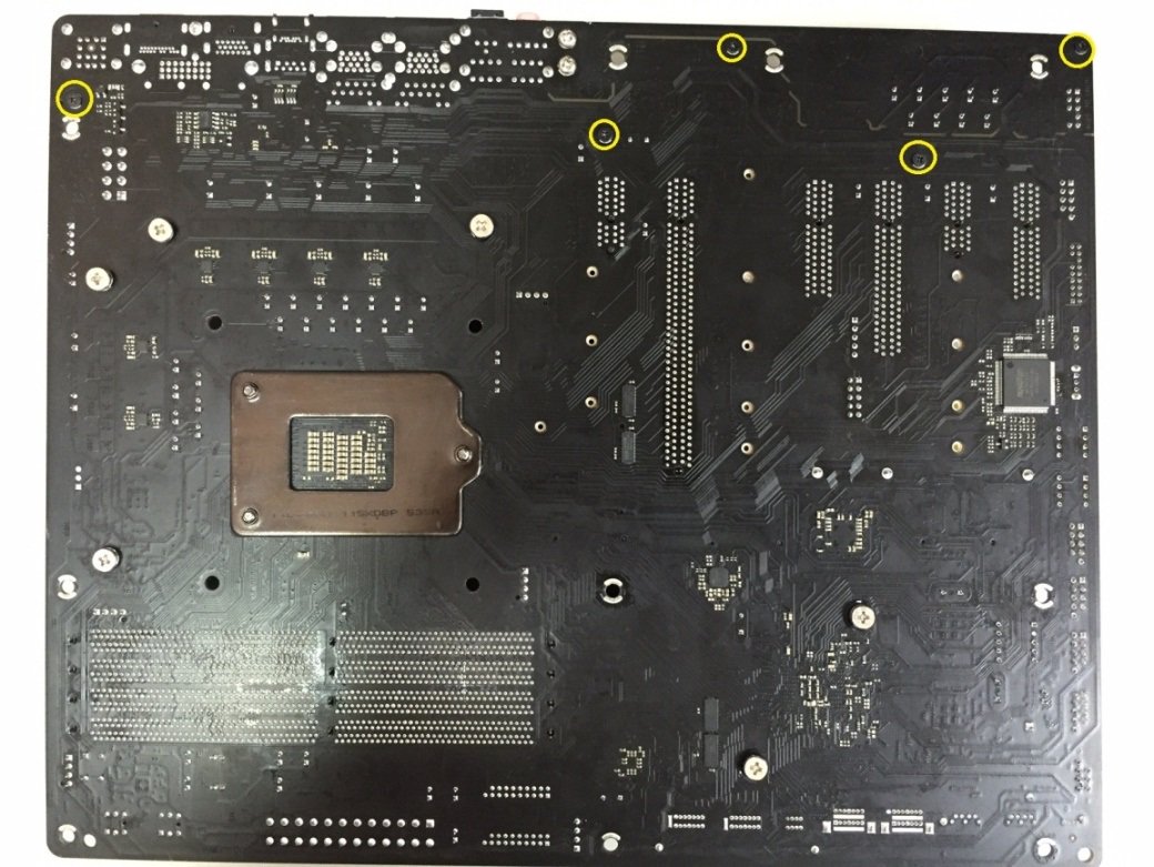
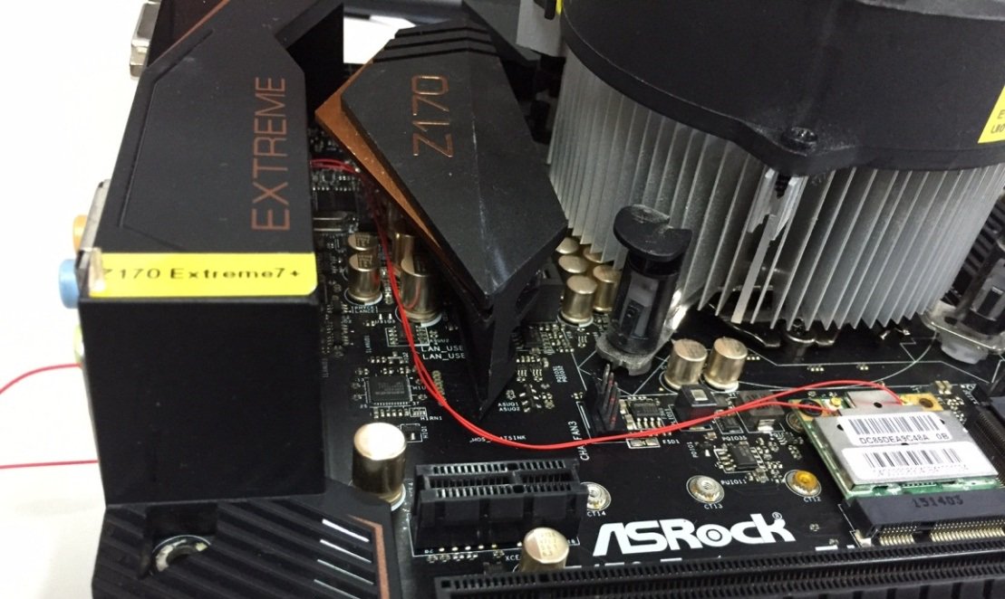
Step 2 –Route the red wires as the picture below to connect the WiFi antennas and mini-PCIe WiFi card. 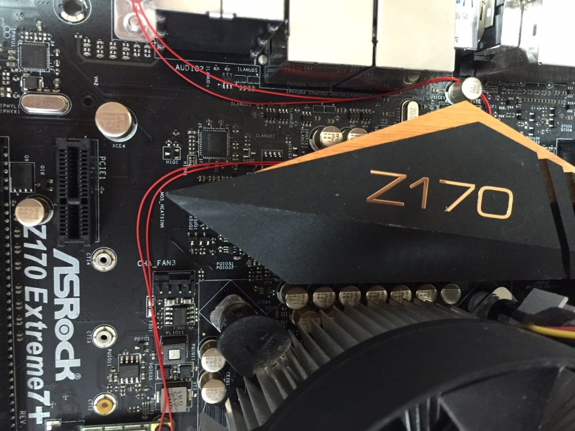
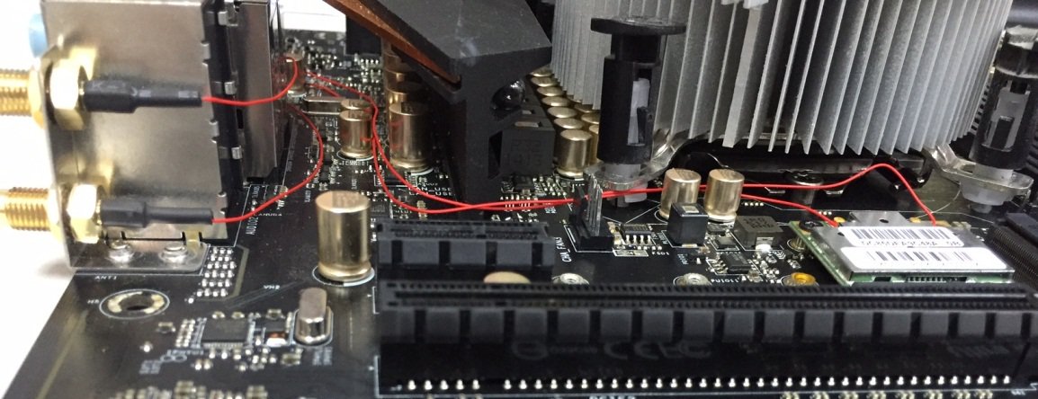
Step 3 – Install the IO cover back to Z170 Extreme7+ as below picture.
Answer:
Please visit ASRock Download zone and update the BIOS to the following BIOS or later versions.
Download link: https://www.asrock.com/support/download.asp
| Model | BIOS Version |
| Z170 Extreme6+ | P1.80 |
| Z170 Extreme6 | P1.80 |
| Z170 Gaming K6+ | P1.90 |
| Z170 Gaming K6 | P1.90 |
After installing the OS, follow the steps below to activate Windows 10 Home 64-bit.
2. Unzip the tool and launch it. 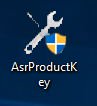
3. You will receive the product key of your system as shown below.
4. Type «Activation» on Windows search and press enter. 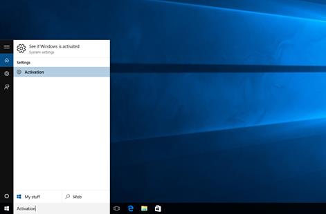
5. Click «Change Product Key» and enter the key which was displayed at step3.
6. After entering the Product Key, the OS will be activated.
Answer:
Step 1. Open the CPU socket without removing the CPU protection cover: Disengage the levers on both sides by pressing it down and sliding it out of the hook. 
Step 2. Insert the LGA 2011-3 CPU: Make sure that you locate Pin1 and the two orientation key notches to where they belong, and then carefully place the CPU into the socket. 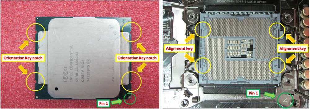
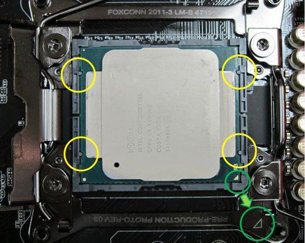
Step 3. Close the socket: Press down the levers on both sides, and secure them under the retention tab. The protection cover will automatically come off by itself.

Answer:
Please refer to the following steps to update the BIOS from ASRock’s website.
| Model | BIOS Version |
| X99 Extreme3 | P1.80 |
| X99 Extreme4 | P1.80 |
| X99 Extreme6 | P1.80 |
| X99 Extreme6/ac | P1.60 |
| X99 Extreme11 | P1.10 |
| X99 OC Formula | P1.80 |
| X99 Professional | P1.60 |
| X99 WS | P1.70 |
| X99 WS-E | P1.20 |
| X99 WS-E/10G | P1.20 |
| X99M Extreme4 | P1.70 |
| X99M Killer | P1.80 |
| X99X Killer | P1.80 |
Step 1. Please remove all unnecessary PCI-E devices including 1 R9 295×2 VGA card, and only install one VGA card onto the system as a display output.
Step 2. Boot up the system and then enter into BIOS setup.
Step 3. Please load the BIOS default settings and then save the settings.
Step 4. Enter into BIOS setup and choose «Instant Flash» to upgrade to the latest BIOS
Step 5. After successfully updating the BIOS, please install the second R9 295×2 VGA card onto your system.
Answer:
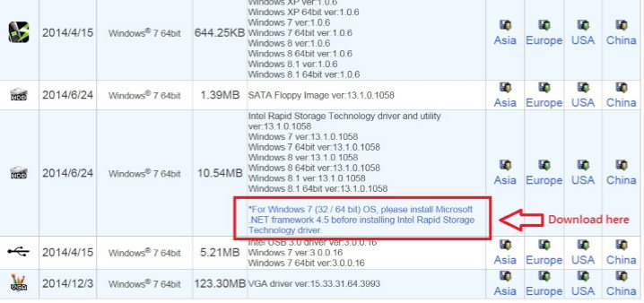
Rapid Storage Technology version 13.1.0.1058 requires Microsoft .NET framework 4.5 to install, please download and install Microsoft .NET framework 4.5 before installing Rapid Storage Technology.
Answer:
Step 1:
Please make sure that you have installed the latest BIOS and two 1866MHz or higher frequency memory modules in dual channel.
Also keep the default UEFI setting of «Dual Graphics» option on [Auto].
BIOS download link: https://www.asrock.com/support/download.asp
Step 2:
Install one AMD RADEON PCI Express graphics card to the PCIE slot.
Step 3:
Connect the monitor cable to the onboard VGA port. Please note that the current VGA driver / VBIOS allows Dual Graphics output from the onboard display only.
For any future update, please refer to our website for further information.
Step 4:
Boot into the OS.
Then please remove the AMD driver if you have any VGA driver installed in your system.
Step 5:
Install the onboard VGA driver from our support CD to your system for both the onboard VGA and the discrete graphics card.
Step 6:
Restart your computer. Right-click the desktop. Click «AMD VISION Engine Control Center» to enter AMD VISION Engine Control Center. 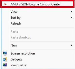
Step 7:
You can also click «AMD VISION Engine Control Center» on your Windows taskbar to enter AMD VISION Engine Control Center. 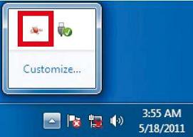
Step 8:
In AMD VISION Engine Control Center, please choose «Performance». Click «AMD CrossFire™». 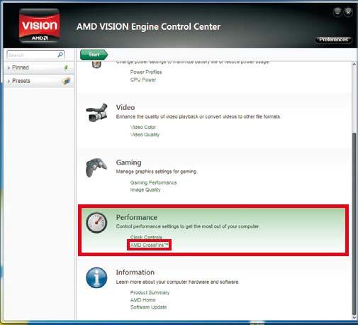
Step 9:
Click «Enable CrossFire™» and click «Apply» to save your change. 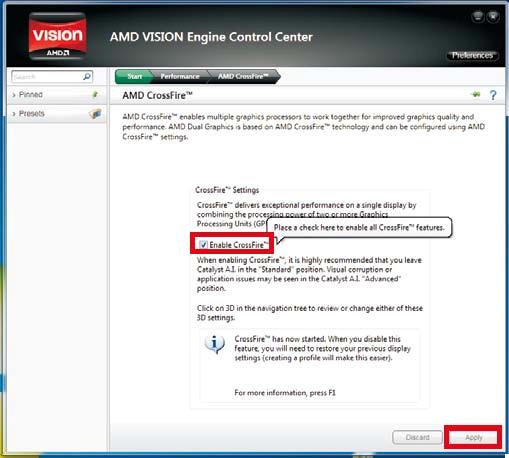
Step 10:
Reboot your system. Then you can freely enjoy the benefit of Dual Graphics feature.
Question (359): When enabling ASRock A-Tuning, I get two error messages below: Assertion failed: m_strCurrentPath.Length() > 0, file Module\OMG\Registry.cpp, line 372 Abnormal program termination.
How do I solve this problem? 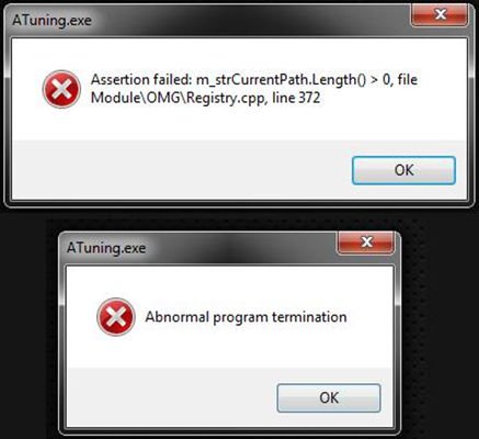 (12/1/2013)
Question: When enabling ASRock A-Tuning, I get two error messages below: Assertion failed: m_strCurrentPath.Length() > 0, file Module\OMG\Registry.cpp, line 372 Abnormal program termination.
How do I solve this problem? (12/1/2013)
Answer:
Please follow the steps below to enable Teaming
Step1: After installing the motherboard and LAN drivers, restart your computer and then open Device Manager.
Right click on the network adapter and select Properties under Network adapters. 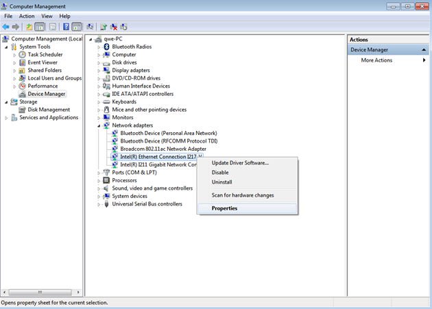
Step 2: Click the Teaming tab, select the Team this adapter with other adapters checkbox, and click New Team. 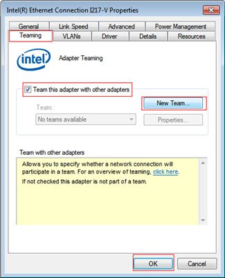
Step 3: Enter the team name. 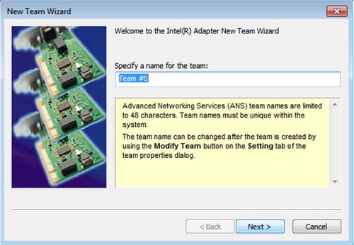
Step 4: Select two adapters to include in the team and click Next. 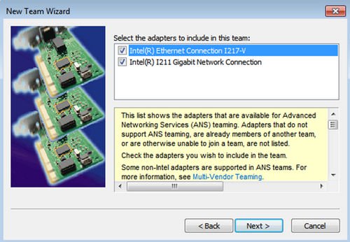
Step 5: Select a team type and click Next. You can read the detailed explanation of each team type below.
On the following dialog box, click Finish to complete the teaming configuration. 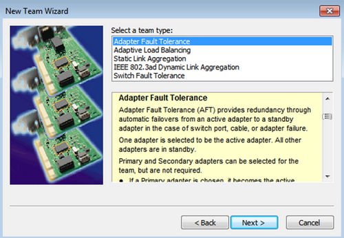
Adapter Fault Tolerance:
The team will use the healthiest high-speed adapter as primary adapter; the other adapter is in standby. If the active adapter fails, the secondary adapter takes over.
Adaptive Load Balancing:
Provides transmit traffic load balancing and fault tolerance. The team will analyzes the transmit load on each member adapter and balances the traffic across member adapters
* Static Link Aggregation:
A performance technology developed to increase throughput between switches or a server and switch. This is accomplished by bundling or channeling several ports together and showing them as a single link. This increases the total bandwidth.
* Switch (or Router) could support Teaming (IEEE 802.3ad LACP) function
* IEEE 802.3ad Dynamic Link Aggregation:
An IEEE standard for increasing throughput between switches or a server and switch. This is accomplished by dynamically bundling or channeling several ports together and showing them as a single link using Link Aggregation Control Protocol (LACP). This increases the total bandwidth.
* Switch (or Router) could support Teaming (IEEE 802.3ad LACP) function:
Switch Fault Tolerance: Primary adapter will automatically fail over to a standby adapter
Note: If you want the team with double bandwidth, please select Static Link Aggregation or IEEE 802.3ad Dynamic
Step 6: You can see the new team under Network adapters.
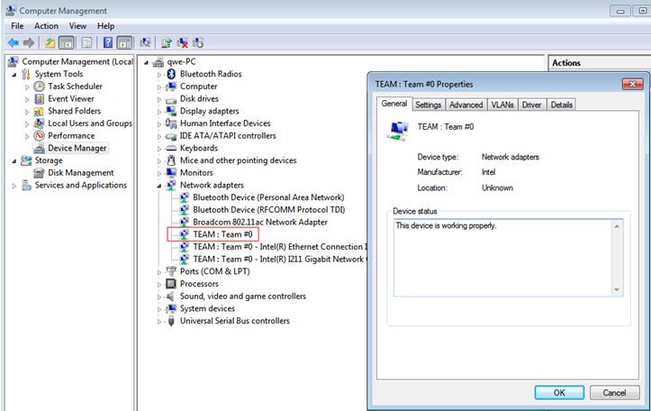
(Note: To delete the team, right click on the team and select Properties\Settings\Remove Team.)
Answer:
You may follow the steps below:
1. Please load default settings for the BIOS and make sure your system is connected to the Internet.
2. If your Internet environment is PPPoE, please enter «Network Configuration item».
Select «Internet Setting» as «PPPoE» then type in your name and password. 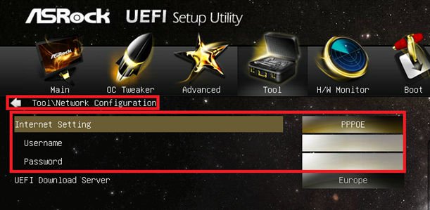
3. You can select the UEFI Download Server nearest to you. 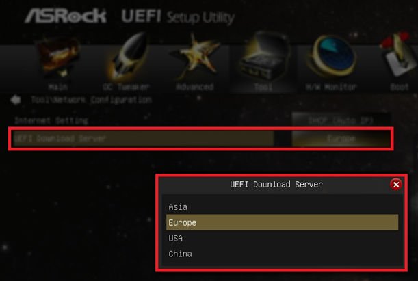
4. If the same problem still occurs, please download and update the latest BIOS from ASRock’s website first, then you can update the BIOS via Internet Flash next time.
Download link: https://www.asrock.com/support/download.asp
Answer:
Please follow below steps to use WOL function.
1. Please enable «Onboard LAN power on» in BIOS\Advanced\ACPI configuration.
2. Connect LAN cable.
3. Search terminal in Dash Home and open it. 
4. Please install ethtool to enable WOL by following command. (Refer the picture)
#sudo apt-get update
#sudo apt-get install ethtool
#sudo ethtool –s eth0 wol g
#sudo reboot 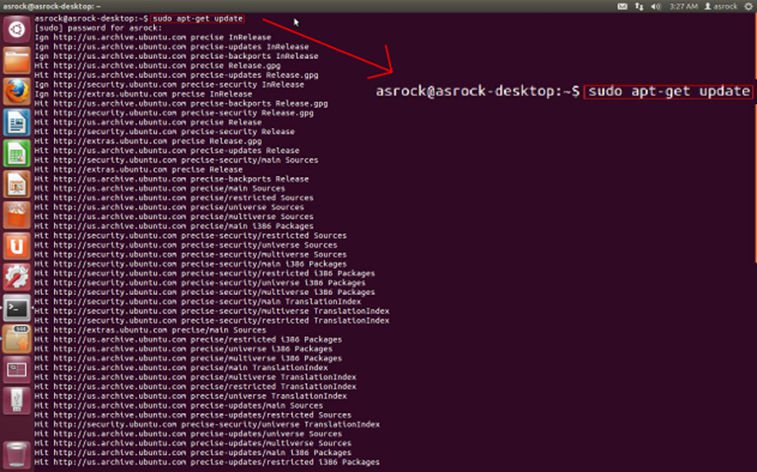
5. Now, the system is ready to be woken up through LAN by other computers.
Answer:
There are two different type of CPU protection cover, please check your CPU protection cover type first then follow below SOP to install CPU.
Type A: CPU protection cover on the top of CPU socket.
Step 1. Open the CPU socket without remove CPU protection cover: Disengage the lever by pressing it down and sliding it out of the hook. At this time, you do not have to remove the protection cover. 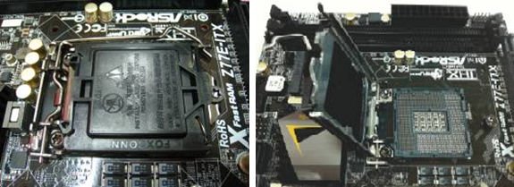
Step 2. Insert the 115x-Pin CPU: Make sure locate Pin1 and the two orientation key notches, then carefully place CPU into the socket. 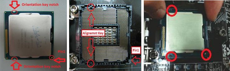
Step 3. Close the socket: Press down the load lever, and secure it with the load plate tab under the retention tab. The protection cover will automatically come off by itself. 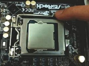
Type B: CPU protection cover in CPU socket.
Step 1. Open the CPU socket: Disengage the lever by pressing it down and sliding it out of the hook. 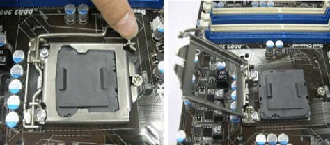
Step 2. Remove CPU protection cover: Attach your index finger to the upper edge of the PnP Cap. Use your thumb to remove PnP Cap (Pick and Place Cap) from the CPU socket by lifting the cap tab. 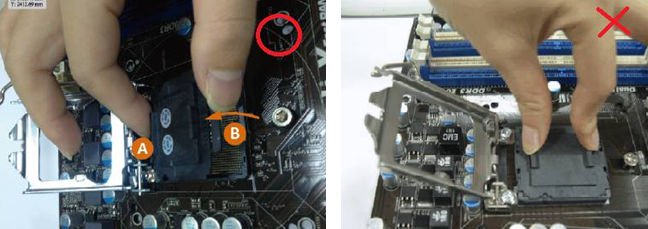
NEVER remove PnP Cap as pictured on the above. Incorrect removal of the PnP cap may cause damage to the CPU socket contacts.
Step 3. Insert the 115x-Pin CPU: Make sure locate Pin1 and the two orientation key notches, then carefully place CPU into the socket. 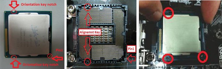
Step 4. Close the socket: Press down the load lever, and secure it with the load plate tab under the retention tab.
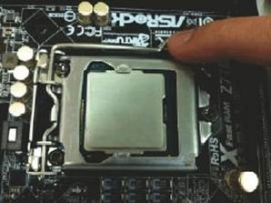
Answer:
Please note that Virtu MVP2.0 available for download and purchase only for Lucid online shop customers.
Please update Virtu MVP 1st generation version.
http://www.lucidlogix.com/driverdownloads-mvp.shtml.
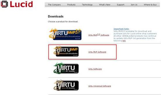
Answer:
If you’ve connected the HDD which contains your operating system on SATA3_A0/ SATA3_A1 ports, please use the Windows 8 inbox driver. 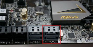
Or you could connect the HDD to SATA3_0/ SATA3_1 ports and install ASMedia SATA3 driver again. 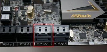
Answer:
Please make sure that you meet the required conditions listed below.
1. The DVI port on the motherboard must support HDCP.
If you aren’t sure about the DVI port’s specifications, please refer to the specification for your M/B on our website. 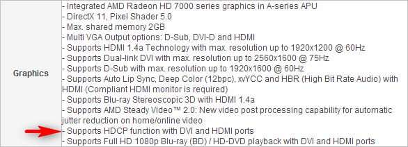
2. Connect a DVI to HDMI adapter.
3. Adjust the DVI function option to [as HDMI] in BIOS\Advanced\North Bridge Configuration. 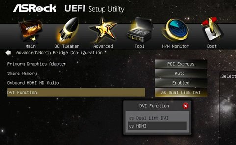
4. Set HDMI as default playback device in Control Panel\Sound.
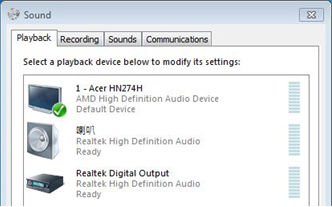
Answer:
Dr. Debug is used to provide codes that represent different errors that your system has encountered. Please see the diagram below for reading the Dr. Debug codes and how to troubleshoot.
| Code | Description |
| FF, 00 — 19 D0 — D3 |
Please check if the CPU is installed correctly and then clear the CMOS. |
| 31 — 3B 51 — 55 |
Problem related to CPU and memory. Please clear the CMOS. Re-install the CPU and memory. |
| D4 — D5 | PCI resource allocation error. Out of Resources. |
| D6 92 — 97 |
The graphics card or iGPU could not be recognized. Please clear CMOS and try re-installing the graphics card. If the problem still exists, please try installing the graphics card in other slots or try other graphics cards. |
| D7 | The keyboard and mouse could not be recognized. Please try re-installing the keyboard and mouse. |
| D8 | Invalid password |
| 9A — 9D | Problem related to USB devices. Please try removing all USB devices. |
| E8 — EB | S3 Resume failed (S3=Sleep) |
| 03 | System is entering S3 state (S3=Sleep) |
| 04 | System is entering S4 state (S4=Hibernate) |
| 05 | System is entering S5 state (S5=Soft power off) |
| 30 | System is waking up from S3 state (S3=Sleep) |
| 40 | System is waking up from S4 state (S4=Hibernate) |
| AA | System is entering OS |
Answer:
Please enter the UEFI SETUP UTILITY to enable IGPU Multi-monitor in Advanced/North Bridge configuration (refer to the picture) before installing the Intel VGA driver.
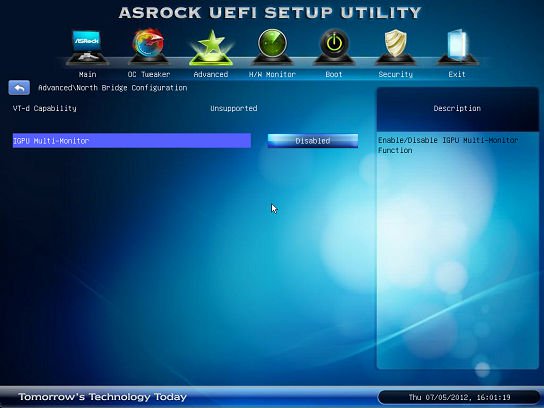
Answer:
The GTX690 has two GPUs that will work together in Maximum 3D performance mode.
You have to connect your monitors to DVI_2 & DVI_3 which come from the same GPU.
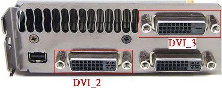
Answer:
Please disable all bootable devices under BIOS, then save and leave. 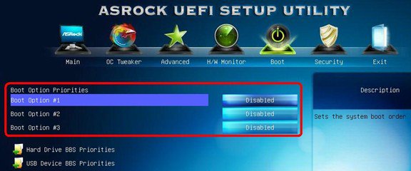
When system boot up, please press to enter LSI RAID ROM. 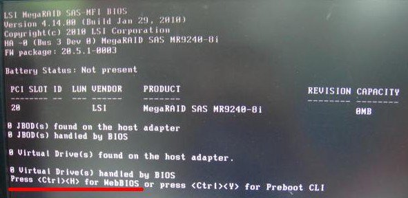
After setup finish, in order to restore bootable devices, please enter BIOS again and load BIOS default.
Answer:
Since there are some VGA cards with incorrect information in vBIOS (Video BIOS), please contact your VGA card vendor or update motherboard BIOS to latest version from our website: https://www.asrock.com/support/download.asp
If you have any question, please contact ASRock TSD.
Answer:
Please follow below two methods to connect HDD and ODD on corresponding SATA port.
Method1: If you connect HDD on SATA3_0 port, please connect ODD on SATA2_2 or SATA2_4 ports.
Method2: If you connect HDD on SATA3_1 port, please connect ODD on SATA2_3 or SATA2_5 ports.
Please refer below table for detail:
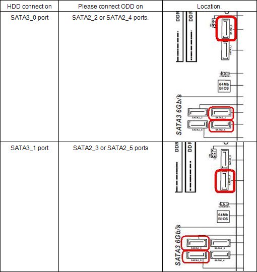
Answer:
Please follow below SOP to install Windows Vista/7 64bit OS on the RAID volume:
Step 1: Flash BIOS to latest version.
Step 2: Connect all HDDs then do below settings:
Set [SATA Mode] as [RAID Mode]
Change [Onboard RAID 3TB+ Unlocker] to [EFI Compatible ROM]
The options are located in BIOS > [Advanced] > [Storage Configuration]
Then press F10 to save settings.
Step 3: Press F11 during boot up and choose boot to [Built-in EFI Shell].
Step 4: Key in «drvcfg», and you will see the information like below:
Drv[4E] Ctrl[B5] Lang[eng] 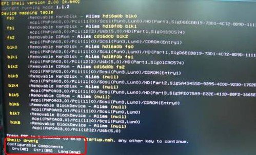
Step 5: Key in «dh [Drv number]», for example: key in «dh 4E».
Step 6: Key in «drvcfg –s [Drv number] [Ctrl number]» to enter Raid Utility.
For example: key in «drvcfg –s 4E B5» 
Step 7: Choose [Logical Drive Main Menu] to set up Raid Drive.
Step 8: Choose [Logical Drive Create Menu] to create a Raid Drive. 
Step 9: Choose [Usable Physical Drive List] to select Raid HDD. 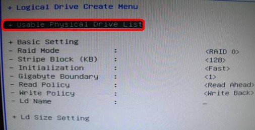
Step 10: Press Space on keyboard to toggle checkbox. 
Step11: Choose [Ld Size setting], and key in the Raid size.
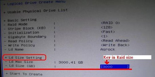
Step12: After set up Raid size, please click [Start to Create] 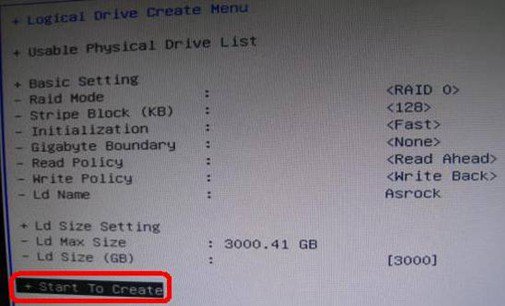
Step13: Press «F10» to Exit Utility.
Step14: During reboot, please press «F11» to enter Boot Menu.
Choose UEFI: CD/DVD Drive 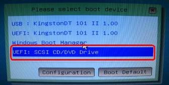
* This option only shows on Windows7 64bit and Vista 64bit OS.
Step 15: Follow Windows Installation Guide to install OS.
Please load latest SATA RAID driver ver.3.3.1540.22 during OS installation from our website
Step 16: Install latest drivers from ASRock website.
Answer:
For support Intel next generation 22nm CPU, it required correspond BIOS version, drivers, and AXTU update.
Please follow below steps to update correspond BIOS, drivers and Utilities.
Step 1: Check BIOS version.
Please check below table and update BIOS since or higher version.
If you have the same or a higher BIOS version on your motherboard, there is no need to update the BIOS and you can skip step 2.
| Model | BIOS Version |
| H61M-VS R2.0 | P2.10 |
| H61M-HGS | P1.50 |
| H61M-HVS | P1.90 |
| H61M-HVGS | P1.70 |
| H61M/U3S3 | P1.70 |
| H61M-ITX | P1.60 |
| H61iCafe | P1.70 |
| H61DE/S3 | P1.70 |
| H61DE/SI | P1.70 |
| H61M-PS | P1.40 |
| H61M | P1.70 |
| H61DEL | P1.70 |
| H61M-GE | P1.70 |
| P65iCafe | P1.40 |
| H61M-VS | P2.10 |
| H61M-S | P1.50 |
| H61M-GS | P1.50 |
| Model | BIOS Version |
| Fatal1ty Z68 Professional Gen3 | P2.10 |
| Z68 Extreme3 Gen3 | P2.10 |
| Z68 Extreme4 Gen3 | P2.10 |
| Z68 Extreme7 Gen3 | P2.10 |
| Z68 Pro3 | P2.10 |
| Z68 Pro3 Gen3 | P2.10 |
| Z68 Pro3-M | P2.10 |
| Z68M/USB3 | P2.10 |
| Z68M-ITX/HT | P2.20 |
| Z68 Extreme4 | P2.20 |
| Model | BIOS Version |
| Fatal1ty P67 Performance | P2.10 |
| Fatal1ty P67 Professional | P3.10 |
| P67 Extreme4 | P3.10 |
| P67 Extreme4 Gen3 | P2.10 |
| P67 Extreme6 | P2.10 |
| P67 Pro | P2.10 |
| P67 Pro3 | P3.10 |
| P67 Pro3 SE | P2.10 |
| Model | BIOS Version |
| H67DE3 | P2.10 |
| H67M | P2.10 |
| H67M-GE | P2.10 |
| H67M-GE/HT | P2.10 |
| H67M-ITX | P2.10 |
| H67M-ITX/HT | P2.10 |
There are two ways to check BIOS version.
1. Boot up your system and press [F2] or [Delete] when ASRock boot logo showing up, you can find the BIOS or UEFI version in the main screen as below. ![press [F2] or [Delete] when ASRock boot logo showing up](https://www.asrock.com/support/faq/201202-5.jpg)
2. Or find the sticker on BIOS ROM chip as below, you can check which BIOS version implemented when motherboard produced. 
Step 2: Updating the BIOS
A), If you have a Sandy Bridge CPU or if you can borrow one from a friend then you can easily update the BIOS yourself.
Please download BIOS from above table, and update BIOS.
For further instructions please click on the «How to update» icon in the corresponding row. ![click on the [How to update] icon in the corresponding row](https://www.asrock.com/support/faq/201202-7.jpg)
B), If you do not have a Sandy Bridge CPU and you cannot borrow it, please contact the dealer where you bought from to update the BIOS for you.
That is the second fastest option to get your board to support the Ivy Bridge CPU.
If that is not possible then please contact ASRock Technical Support for further help.
*Note: If you use a USB flash drive to update BIOS, after new BIOS image has been written to the chip, please press any key to restart system. At this moment, please do not remove the USB flash drive. Intel ME firmware update procedure will proceed automatically if it is required.
**Note: Please only use the BIOS image offered on ASRock website.
Step 3: Update suitable Intel HD graphics driver from ASRock website
*How to update Intel HD graphics driver:
1. Please unzip and open the folder to execute «setup».
2. Follow Intel driver installer to install the graphics driver.
3. After the installation has finished you will see below message, please restart your system at this moment.
Step4: Install the correct version of Intel Management Engine from ASRock website:
*How to update Intel Management Engine:
1. Please unzip and open the folder to execute «setup».
Route: Enter Intel ME8 folder-> ME8_1.5M_8.0.0.1351-> Installers-> ME_SW-> Choose «Setup».
2. Follow Intel driver installer to install the ME driver.
3. After the installation has finished, you will see below message. Please click on «Finish».
Step 5: Install Intel Smart Connect driver for Microsoft Windows7/7 64 bit. OS.
Step 6: Update ASRock AXTU Utility.
Please update new AXTU version on ASRock website.
Step 7: Replace CPU to Intel Ivy Bridge.
Answer:
Please follow below steps:
Step 1. Add » nomodeset» parameter before installing. (a space, then nomodeset)
Step 2. When you boot for the first time from HDD after installation, please press shift when booting up until the GRUB menu shows up.
Step 3. Press «e» to edit the option. Replace «quiet splash» with «nomodeset».
Step 4. Press Ctrl+X to continue booting process.
Step 5. Connect to Internet and start updating drivers for the graphic card.
[System Settings] > [Hardware] > [Additional Drivers] > Activate [NVIDIA accelerated graphics driver]
Answer:
Requirements:
OS: Windows7, Vista SP2 or later.
Receiver / decoder: Onkyo TX-SR608 amplifier for example:
Playback software: for example Power DVD10 v10.0.2025.52 or other playback software.
Setup:
1. Please install all drivers from support CD, after that please check device manager, there should be no any «!» or «?» on list.
2. Please enter Control Panel > Hardware and Sound > Sound,
If you would like to output via HDMI, please select [HDMI output]
If you would like to output via SPDI, please select [Digital output] 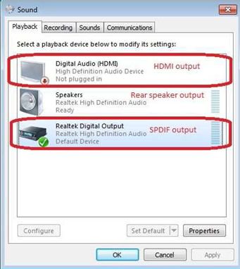
*Different motherboard/chipset may show different information, above picture is for references only.
3. Enter the Audio settings in your application.
We take Power DVD 10 here for example: Choose the Speaker environment and Output modes as you want. 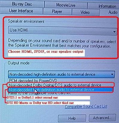
4. Set your decoder/amplifier to the digital sound output, which you want.
5. Set the correct output format on your content /source manual. 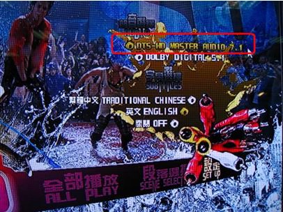
6. Then you can play the content/source.
Answer:
Different monitor/TV/content/playback software may have different settings.
We use below for example:
3D TV: Samsung UA46C7000WM 46″
Play back software: Power DVD10 v10.0.2025.52
Play back content: Step UP 3D blu-ray
1. Please follow below steps to setup under OS.
A. Please install all drivers on SCD before following steps in this setup guide.
B. Please right click on desktop, and enter NVIDIA Control Panel.
C. Select «Setup Stereoscopic 3D task» in NVIDIA Control Panel, and check to «Enable Stereoscopic 3D»
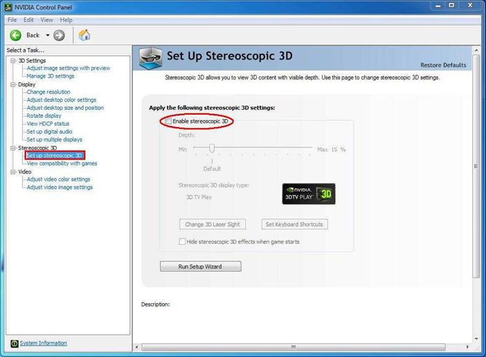
D. If it’s the first time for you to setup 3D feature, the system may lead you to run Setup Wizard. Please follow the instruction and finish the Setup Wizard.
E. After finishing the Setup Wizard, please enter Display > Change Resolution, set the resolution to «HD, 3D» with proper solution and «Refresh rate».
We set it as «1080p» and 24Hz during our tests.
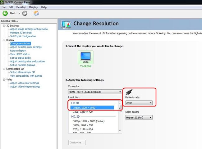
F. Click «Apply» to save the changes.
2. Please follow below steps to setup your PowerDVD10
A. Click on the arrow right next to the «3D» icon on PowerDVD10 to start 3D Display Configuration.
B. Set the proper type of your monitor / TV in Display Device. As shown in picture below, we select 120Hz Time-sequential 3D LCD for example.
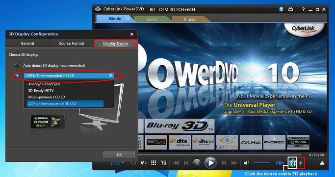
* Note: Please note that different monitor/TV/content may have different settings; please check user manuals of your monitor / TV/content for further details.
C. Then you can play the 3D content.
Answer:
Please download SOP of VT-d test from the link below for reference,
https://www.asrock.com/support/note/vt-d.pdf
※ System requirements are listed below,
i. 2048MB or larger of RAM (Minimum system requirements of VMWare)
ii. K-series CPU does not support VT-d
Answer:
Please kindly refer to below picture to disable «Automatically download Windows Media Center data between the following times» option under MCE.
(Path: MCE-> Task->Settings-> General->Automatic Download options-> Automatically download Windows Media Center data between the following time.)
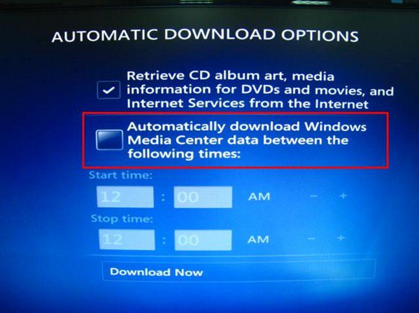
Answer:
Please install OS both in GPT or MBR mode.
Both in GPT mode, please refer below steps:
1. Boot into BIOS→[Boot]→[PCI ROM Priority]→choose [EFI Compatible ROM], then press «F10» to save changes and exit.
2. Then press «F11» when booting up and choose «UEFI:[your ODD name]» to install OS.
Both in MBR mode, please refer below step:
Please press «F11» when booting up and choose «AHCI/SATA:[your ODD name]» to install OS.
Answer:
First, please download and update BOTH of your BIOS and Intel Rapid Storage Driver.
After doing so, please follow the steps below to setup Intel Smart Response:
Step 1. Before booting up the system, please make sure to connect your HDD to supported SATA ports.
For Z68 Extreme4, please connect to the ports as shown below.
These ports are from Intel PCH chipset, which support Intel Smart Response Technology. 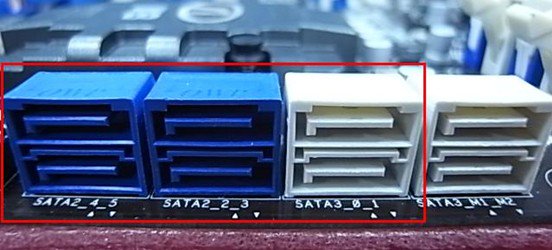
Please note that, for Z68 Pro3 or Z68 Pro3-M, all the SATA ports are supported.
※ Note:
We recommend users to connect your HDD to SATA3 ports if your HDD is SATA3 spec.
Please DO NOT connect SSD to the system at the moment.
Step 2. Please press F2 or DEL to enter BIOS > Advanced > Storage Configuration.
Step 3. Please set SATA mode to [RAID Mode] as shown below 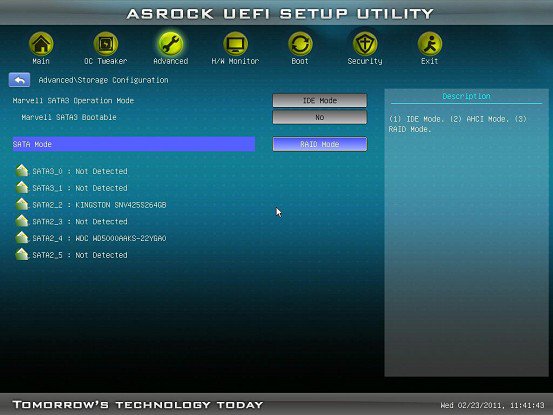
Step 4. In RAID ROM screen, HDD status should be «Non-RAID Disk»
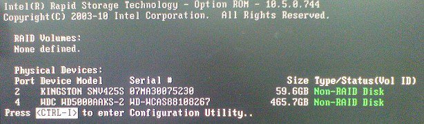
Step 5. Please install OS in SATA HDD, after installation, please shut down your system and connect SSD to SATA ports listed above.
Step 6. Please install Intel Rapid Storage Driver (10.5.0.1027)
Step 7. After installation is completed, reboot the system and open Intel Rapid Storage Technology. 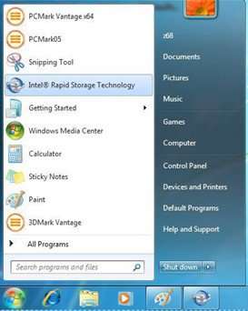
Step 8. Choose «Accelerate», and click «Enable acceleration»
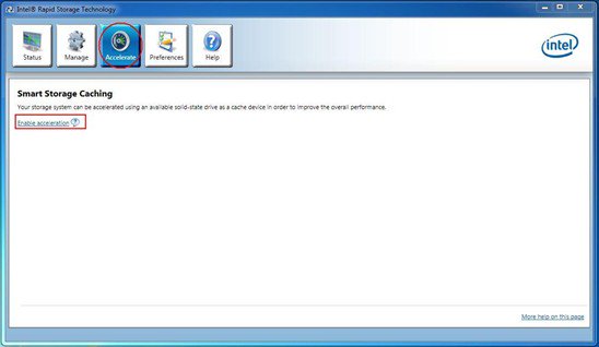
Step 9. You could change the default settings as you want it, then click «OK»
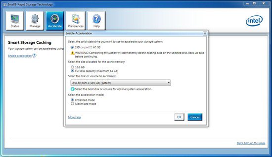
Step 10. You could see the Smart Storage Caching is enabled as shown below:
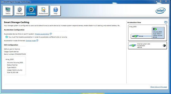
Answer:
Please refer to below form for the beep code and debug code of AMI UEFI BIOS.
| Condition | Beeps Code | Debug Code |
| Normal | No beep | With goodnight LED enabled, debug code will disappear after the beep. |
| Bad CPU | No beep | No debug code |
| Bad memory | No beep | 45 |
| Without memory | 3 long beeps | 53 |
| Without CPU | No beep(No Power) | No debug code |
| Without VGA card | 5 long beeps | Beeps at»d6″, then show «0d» |
Answer:
Please kindly follow the steps as below to remove «Accusys Inc- Storage- ACS-6xxxx».
Step1. Click «Start» -> «Computer» -> «Manage». 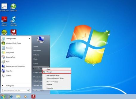
Step2. Click «Device Manager» -> «ACS-6xxxx» -> «Properties». 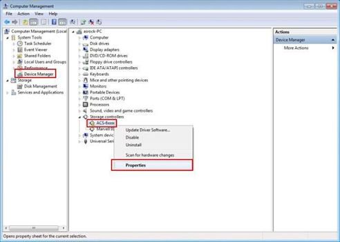
Step3. Click «Uninstall». 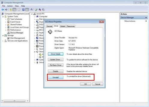
Step4. Enable «Delete the driver software for this device» option and then press «OK». 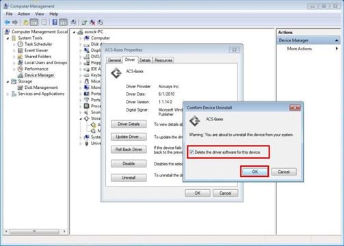
After uninstalling the driver of ACS-6xxxx and rebooting the system, the LAN controller will work normally.
Answer:
The shared memory size is dynamically controlled by VGA driver, and the maximum share memory size will be available only when more than 4GB memory is installed under 64-bit OS. Please kindly refer to the following steps to check the maximum graphic share memory.
1.Visit the «Display» option in the control and choose «Advanced setting».
2.Choose «»Intel ® Graphic and Media Control Panel.
3.Click the «Graphic Properties.’
4.Visit the «Option and support» and choose «Information Center».
5.Then you could see the information at the right side. 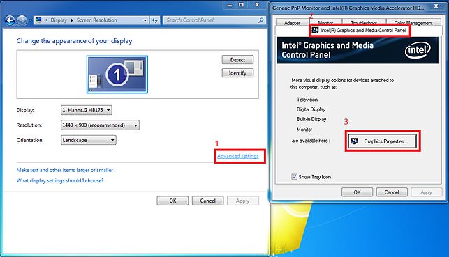
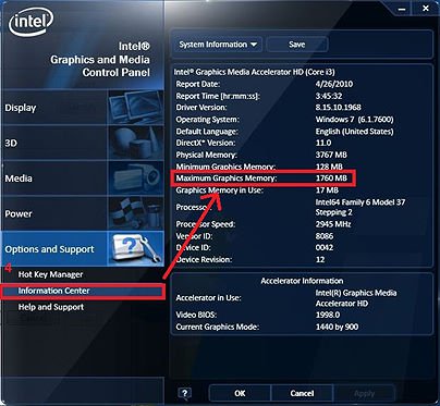
Answer:
USB3.0 and USB2.0 cable has some differences, please refer below picture to check your USB cable is USB2.0 or USB3.0 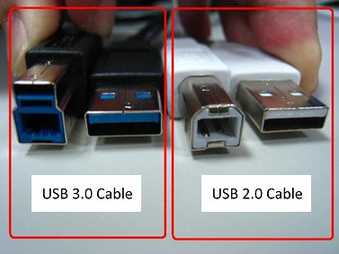
If you connect USB2.0 cable on USB3.0 external HDD device like below, it will not run at SuperSpeed mode.
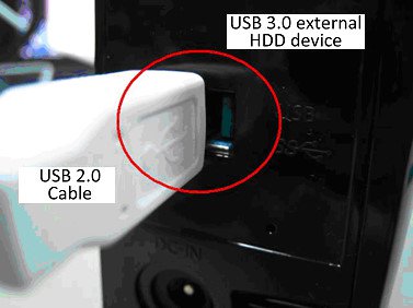
Please connect USB3.0 cable on USB3.0 external HDD device to run at SuperSpeed mode.
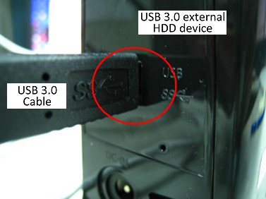
Answer:
Due to the Chipset spec., please insert the memory module into the white slot (DDR3_B1) which is nearly CPU socket for the first priority. 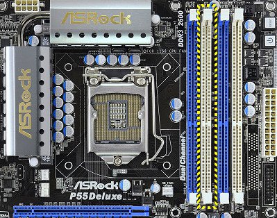
Please insert your DRAM in this slot for the first priority.
Answer:
Some suggestions as below may solve the issue,
1. Please re-install your Windows ® XP and install required driver in such order :
a. HD Audio Driver and Application(VIA ® HD Audio driver)
b. Onboard HDMI HD driver (NVIDIA ® HDMI driver)
c. All in 1 driver.
2. Refering to the attached picture, please install a display driver in support CD -> Others -> Display -> XP32_185.66 -> Setup.exe 
3. Please check your VGA driver version has been update to 6.14.11.8576 by device management. 
4. Since when ever you plugged the rear speaker to ION330, the sound playback would AUTOMATICALLY set to «HD Audio Rear Output», therefore, during the test, please ONLY connect HDMI to the TV, and make sure the sound playback is set to «NVIDIA ® HD Audio»
Answer:
ION330 can support Dolby Digital 5.1, DTS 5.1 and LPCM 7.1 only under Windows ® Vista™ or later version.
Please refer to below steps to setting your system.
1. Please update the HOTFIX: KB959458 or update your Vista Service Package to SP2.
Hotfix download link: http://support.microsoft.com/kb/959458
2. Install the drivers in the order listed as below
a. VIA ® HD Audio Driver 7100d
b. NVIDIA ® HD Audio driver 1.0.0.51
c. NVIDIA ® nForce All in 1 v20.14
3. Install a proper AP, we used PowerDVD 9.0 for tests here.
4. Enter Control Panel -> Sound -> Configure to choose Stereo, 5.1.
5. Enter Control Panel -> Sound -> Properties to set the sampling rate, Max Fs. for Dolby-Digital DTS is 48 KHz. 
6. RIGHT CLICK in PowerDVD -> Settings -> Audio 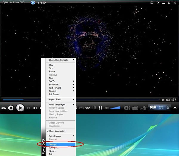
a. Speaker Environment -> Use HDMI (Current Vista Setting)
b. Output Mode -> Non-Decoded DD/DTS to external device. 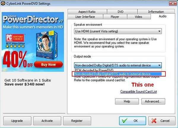
7. RIGHT CLICK in PowerDVD -> Settings -> Video. Enable Hardware Acceleration 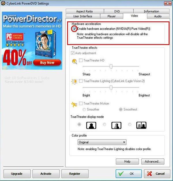
8. As you can see in the picture below, the audio output is Dolby Digital 5.1. 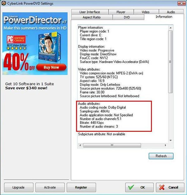
*If you want to output DTS 5.1, please select it in audio menu of DVD.
*For your information, the source of the test is a DVD which supports both DD5.1 and DTS 5.1.
- If your monitor has «PC mode», please try to adjust monitor to PC mode.
If not, please contact your monitor vender for help. - Or you can do some setting on driver.
A. If you use ATI VGA output, please enter [ATI driver controller] to adjust [Scaling Option]
1. Right check the mouse, and enter ATI driver controller.
2. Find the [Scaling Option] to setting the bar until to fit the size. 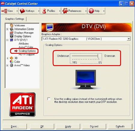
B. If you use NVIDIA ® VGA output, please enter [NVIDIA ® driver controller] to adjust [Resize desktop]
1. Right check the mouse, and enter NVIDIA ® driver controller.
2. Find the [Resize desktop] option to setting the bar until to fit the size.
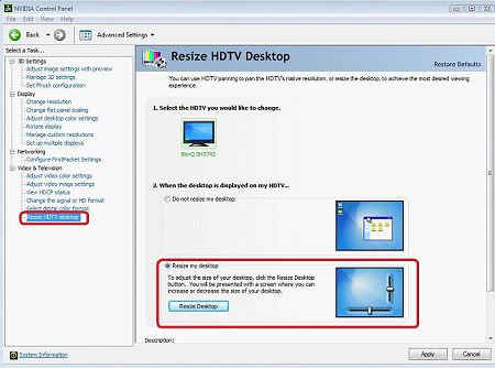
Answer:
Please refer to the steps as below to solve the issue.
1.Please download a registry from the link as below,
https://download.asrock.com/Drivers/others/NVUSBS3.zip
2.Referring to the picture, please double click on the file NVUSBS3, and click YES. 
After the registry is complete, a window may shows up, please press OK and RESTART your computer.
3.Referring to the picture, double click on Keyboard and Mouse in START -> Control Panel.
4.Referring to the picture, move to Hardware tags as 1. and 3., click on Properties as 2. and 4.
5.Referring to the picture, move to Power Management tag as 1. and 3.
Check Allow this device to bring the computer out of standby in BOTH Keyboard and Mouse windows, as 2. and 4. 
6.Now it’s available for you to bring your computer from S3 and S4 with your USB keyboard and mouse.
Answer:
Please kindly refer to the following suggestions:
First, push the power button for three times.
Please power on the ION330 then off it for three times.
Press during post screen and go into BIOS to load BIOS defaults.
If you still have black screen, please try to clear CMOS.
Please open the upper chassis and remove the DVD-OM device.
Answer:
Due to the NVIDIA ® chipset specification, the HDD driver is requirement, please install the HDD driver during the installation of operating system.
Please refer to below steps to install the HDD driver:
1. Please download the driver and save the driver to floppy disk, USB driver, CD or DVD.
HDD driver download link : https://www.asrock.com/mb/download.asp?Model=NF6-GLAN&s=AM2
2. Click «Load driver» icon at the «Where do you want to install Windows?» stage. 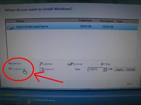
3. Then click «OK» 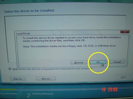
4. Check the icon and click «Brows» 
5. Then choose the driver from the source which you saved. 
6. Select the HDD driver and click «Next» to install the driver.
Question (248): When I plug in an eSATA HDD, it can be recognized in the BIOS. But in the OS, it will show a massage «Storage Device Connected». And I can not use this eSATA HDD, ether. How can I fix it? 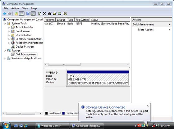 (3/28/2009)
Question: When I plug in an eSATA HDD, it can be recognized in the BIOS. But in the OS, it will show a massage «Storage Device Connected». And I can not use this eSATA HDD, ether. How can I fix it? (3/28/2009)
Answer:
Please follow below steps to set:
1.Please enter Intel ® Matrix Storage Console, and click the mouse right button on eSATA hard device. And press [Reset Hard Drive to Non-RAID]. 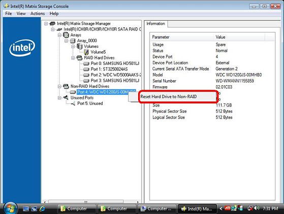
2.After setting [Reset Hard Drive to Non-RAID], please restart your computer.
3.Enter to Disk Management, it can recognize your eSATA HDD, please crate a New Simple Volume on it. 
4.After than, the eSATA HDD can be recognized.
Answer:
Please follow below steps to install your Linux CentOS 5.2 installation.
1.Disable the Onboard LAN 1 and Onboard LAN 2 in BIOS setting.
2.Enter Boot menu and starting the Linux CentOS 5.2 installation.
3.Please install the system packages like below picture. 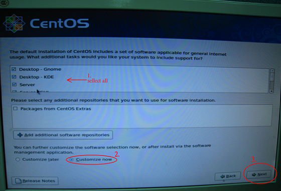
4.After install CentOS 5.2 completely , download your LAN driver by following link.
Link:http://www.realtek.com/downloads/downloadsView.aspx?Langid=1&PNid=13&PFid=5&Level=5&Conn=4&DownTypeID=3&GetDown=false#2
5.Please remove the in-box driver and remove the r8169 LAN driver by following command.
# cp -p r8168-8.011.00.tar.bz2
# tar vjxf r8168-8.011.00.tar.bz2
# cd /lib/modules/`uname -r`/kernel/drivers/net/
# rm -f r8169.ko
# cd
# cd r8168-8.011.00
# make clean
# make modules
# make install
# depmod –a
# reboot
6.After upgrade your LAN driver complete, please reboot your system and enable the Onboard LAN 1 and Onboard LAN 2 in BIOS setting.
Answer:
Due to the operating system limitation, Windows ® XP only supports MBR disk format, the MBR disk format cannot support the hard drive capacity over 2TB.
If you want to use over 2TB RAID volume to be your boot disk, below three conditions must be required:
1.Your operating system must be Windows ® Vista™ x64 SP1 or Windows ® 7 64bit.
2.EFI BIOS.
3.GPT disk format.
Please refer to following link to get more information.
Link:
http://support.microsoft.com/?scid=kb;en-us;946557&x=9&y=7
http://www.microsoft.com/whdc/device/storage/GPT_FAQ.mspx
Answer:
The pin definition of the onboard HDMI_SPDIF header is different from the header of some VGA cards.
Please plug in the HDMI_SPDIF cable reversely like following picture.
Answer:
Please update the C-Media audio driver 8.18.07_SPDIF to fix the problem. The audio driver is available at https://www.asrock.com/mb/download.asp?Model=ALiveDual-eSATA2&s=AM2

Answer:
Before setting Teaming function, please make sure if your Switch (or Router) could support Teaming (IEEE 802.3ad Link Aggregation) function. (For example: D-Link DGS-3100…)
Then, please refer to following steps to set «Teaming function».
1. Install RtkTeaming driver ver.1.0.0.51 from Motherboard Support CD
(/Driver/Teaming/ RtkTeaming 1.0.0.51…)
(*When installing teaming driver, system will show below warming message. Please choose «Continue Anyway» and keep installing driver.) 
2. After installing driver, please open «Teaming Utility» in Programs. (Start > Programs > Realtek > Teaming Utility >…)
3. Click «Teaming» item and then press «Create Team» button. 
4. Key in Team Name and choose «Link Aggregation \ LACP (802.3ad)» for Settings.
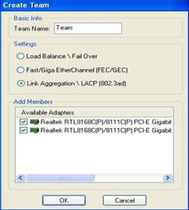
5. Select two available onboard LAN cards and then press «OK» button (After pressing «OK» button, system will show below warming message. Please choose «Continue Anyway».)
6.After doing above settings, system will auto create a new Local Area Connection
7.Reboot system
Then, you will find the «Speed» column of new Local Area Connection will show 2.0Gbps.
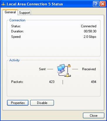
Answer:
VCore on Pentium 4 (and newer generation CPUs) is no longer static. Please refer to the Intel ® document below. It shows that the Vcore will decrease with the CPU loading increasing. That’s why the Vcore may be lower.
Question (232): I install more than 2GB system memory on my system. When I run the «Sound Recorder» under Windows ® XP, it always shows the following error message. What’s wrong?  (7/31/2008)
Question: I install more than 2GB system memory on my system. When I run the «Sound Recorder» under Windows ® XP, it always shows the following error message. What’s wrong? (7/31/2008)
Question (231): When installing NVIDIA GeForce 8400/8500 series PCIE VGA card on K10N78hSLI-WiFi / K10N78hSLI-1394 / K10N78hSLI-GLAN under Windows ® XP/ XP 64-bit, I can not get full system memory. Besides, system shows two display adapters in the Device Manager. What can I do? 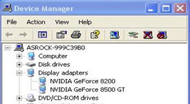 (6/26/2008)
Question: When installing NVIDIA GeForce 8400/8500 series PCIE VGA card on K10N78hSLI-WiFi / K10N78hSLI-1394 / K10N78hSLI-GLAN under Windows ® XP/ XP 64-bit, I can not get full system memory. Besides, system shows two display adapters in the Device Manager. What can I do? (6/26/2008)
Question (230): When I install Realtek HD Audio driver, I found the system shows below error message. What can I do? 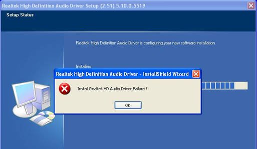 (6/26/2008)
Question: When I install Realtek HD Audio driver, I found the system shows below error message. What can I do? (6/26/2008)
Answer:
Please refer to below steps to reinstall Realtek HD Audio driver:
1.Enter into «Add or Remove Programs» and remove «Realtek High Definition Audio Driver» 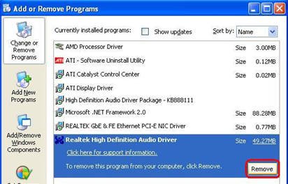
2.Disable all «Microsoft ® UAA Bus Driver for High Definition Audio» in Device Manager first 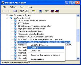
3.Then uninstall all «Microsoft ® UAA Bus Driver for High Definition Audio» from the system.
4.Reboot system
5.Reinstall «Realtek HD Audio driver» from Motherboard Support CD.
If you still meet this problem, please reinstall fresh Windows ® system.
Answer:
Please refer to below suggestions.
If you want to install the Windows ® Vista™ with non-RAID mode:
Install the SATA driver v998 from support CD during the installation of Windows ® Vista™.
The driver path in support CD is
Support CD/Drivers/ SATA2/ nVIDIA/ Vista64_Vista(112)/ IDE/ WinVista/ sata_ide.
Step1:
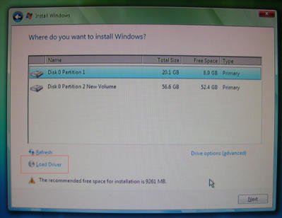
Step2:
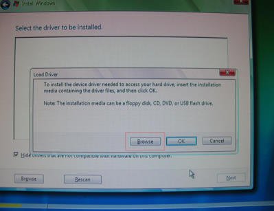
Step3: 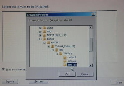
You can also download the SATA driver v998 from ASRock website and save it to a floppy diskette, USB flash drive or CD/DVD disk.
Then install the SATA driver v998 from floppy diskette, USB flash drive or CD/DVD disk during the installation of Windows ® Vista™.
ALiveNF6P-VSTA: https://www.asrock.com/mb/download.asp?Model=ALiveNF6P-VSTA
ALiveNF6G-VSTA: https://www.asrock.com/mb/download.asp?Model=ALiveNF6G-VSTA
ALiveNF6G-GLAN: https://www.asrock.com/mb/download.asp?Model=ALiveNF6G-GLAN
ALiveNF6G-DVI: https://www.asrock.com/mb/download.asp?Model=ALiveNF6G-DVI
AM2NF6G-VSTA: https://www.asrock.com/mb/download.asp?Model=AM2NF6G-VSTA
If you want to install the Windows ® Vista™ with RAID mode:
Please refer to the NVIDIA RAID installation guide.
https://download.asrock.com/Manual/raid/ALiveNF6P-VSTA/English.pdf
Answer:
Please refer to following steps to connect your 5.1 channel speakers:
1. Connect the «Rear Speaker» to Line In (Light blue) port
2. Connect the «Front Speaker» to Line Out (Lime) port
3. Connect the «Central / Subwoofer» to Microphone (Pink) port
4. Adjust the «Audio I/O» setting to «6CH Speaker» in REALTEK Audio Management. Please refer to the following picture:
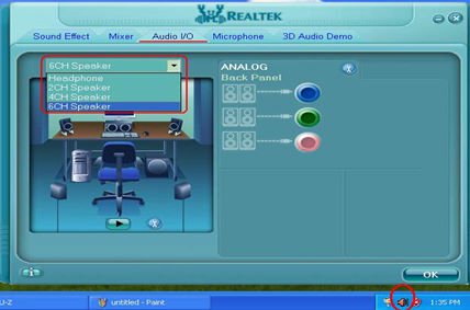
- Only install 2GB memory to the motherboard first.
- Install Microsoft ® Vista Hot Fix KB929777
Microsoft ® Hot Fix KB929777 is available at: http://support.microsoft.com/kb/929777/en-us - After the Hot Fix installation is completed, please restart the Windows ® Vista™ 64-bit system.
- Shutdown the system and install 4GB memories back to the motherboard.
Answer:
Please refer to the following steps to change the channel of software AP. 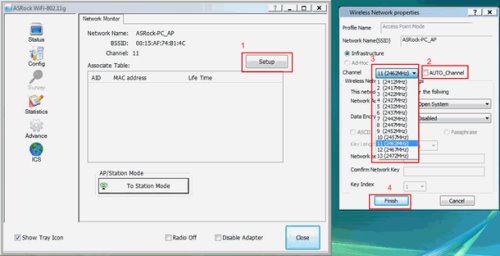
1.Click «Setup» to go into «Wireless Network properties.
2.De-select «Auto_Channel»
3.Choose the channel you want. (suggest to choose the channel 1 or 6 or 11, these channels are less interference with others)
4.Click «Finish» to finish the setup.
Answer:
This is a known issue of Windows ® Vista™ 64 bit. Please install the following two hotfixes from Microsoft. It will solve this problem.
http://support.microsoft.com/kb/938194
http://support.microsoft.com/kb/938979
Please install the Hotfixes according to the following steps:
1.Boot into Windows ® Vista™ 64bit with less than3GB system memory.
(If you are not able to finish installing Windows ® Vista™ 64bit, please install Windows ® Vista™ with less than 3GB system memory)
2.Install the first hotfix, reboot, and then install the second.
3.Reboot the system and let system go into Windows ® Vista™ 64bit.
4.Shut down the computer. And then install the Memory back.
Question (217): My motherboard is 4Core1333-Viiv / 4Core1333-GLAN / 4Core1333-eSATA2. When I install INF driver from Motherboard Support CD, it will show below error message. Is there any way to fix this problem?  (12/19/2007)
Question: My motherboard is 4Core1333-Viiv / 4Core1333-GLAN / 4Core1333-eSATA2. When I install INF driver from Motherboard Support CD, it will show below error message. Is there any way to fix this problem? (12/19/2007)
Question (204): My system is based on P4VM890 / P4VM890 R2.0 with the Integrated VIA ® UniChrome Pro 3D/2D Graphics. When I zoom-in in Google Earth, the picture will get abnormal display (See the following picture). What should I do?
Abnormal display: (black blocks)  (8/3/2007)
Question: My system is based on P4VM890 / P4VM890 R2.0 with the Integrated VIA ® UniChrome Pro 3D/2D Graphics. When I zoom-in in Google Earth, the picture will get abnormal display (See the following picture). What should I do?
Abnormal display: (black blocks) (8/3/2007)
Answer:
Please update the VGA driver to v22.00.01e for fixing this problem. Here are download pages of VGA driver.
P4VM890:
https://www.asrock.com/mb/download.asp?Model=P4VM890&s=478
P4VM890 R2.0:
https://www.asrock.com/mb/download.asp?Model=P4VM890%20R2.0&s=478
Answer:
This is a compatibility issue of ATi Radeon HD 2xxx/3xxx PCIE card and 3DMARK/ PCMARK program.
Futuremark provides 2 solutions for this issue as follows.
Solution 1: Add the command line –nosysteminfo into the target of 3DMARK / PCMARK’s shortcut. 
Solution 2: Rename the «Direcpll.dll» file to something else. (Found in C:\WINDOWS\system32\Futuremark\MSC\Direcpll.dll) 
The link of Futuremark FAQ:
http://service.futuremark.com/support/search.jsp?categoryid=14&search=1
Answer:
1. Please install Vista audio driver. The driver is available from ASRock Web Site.
https://www.asrock.com/mb/download.asp?Model=AM2NF3-VSTA
2. To have the 4/ 6/ 8 channels speaker work normally, it needs to do some settings in Windows ® Vista™. Please refer to following steps.
(1)Please double click the «CM6501 Sound Configuration» icon at the Taskbar. 
(2)Set the System Input as «2 CH». 
(3)Set the Analog Output as corresponding channels that you have. 
(4)Click ok.
Question (198): I have a motherboard with Realtek HD audio codec. After installing the Microsoft ® Security Update 925902 and 928843, my system shows the following error message. How do I fix this?  (4/20/2007)
Question: I have a motherboard with Realtek HD audio codec. After installing the Microsoft ® Security Update 925902 and 928843, my system shows the following error message. How do I fix this? (4/20/2007)
Question (195): I am using the ConRoeXFire-eSATA2/ 775XFire-eSATA2+/ 775XFire-eSATA2/ 775XFire-VSTA/ 775XFire-RAID motherboard. My Operating system was installed in a SATA/ SATA2 HDD with «IDE» mode. When I install the SATA2 driver (Intel ® Matrix Storage Manager), system always pops an error message «This computer does not meet the minimum requirements for installing this software». Why?
IDE mode (In BIOS setup): 
SATA2 driver: 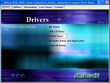
Error Message:  (2/15/2007)
Question: I am using the ConRoeXFire-eSATA2/ 775XFire-eSATA2+/ 775XFire-eSATA2/ 775XFire-VSTA/ 775XFire-RAID motherboard. My Operating system was installed in a SATA/ SATA2 HDD with «IDE» mode. When I install the SATA2 driver (Intel ® Matrix Storage Manager), system always pops an error message «This computer does not meet the minimum requirements for installing this software». Why?
IDE mode (In BIOS setup):
SATA2 driver:
Error Message: (2/15/2007)
UAA Audio (HD Audio, USB Audio and IEEE1394 Audio)
(Premium or Basic depends on Codec Vista logo level)
Second, please kindly refer to below steps to enable Windows ® Aero feature:
1.Press right button of mouse at Desktop and click «Personalize». 
2.Enter into «Windows ® Color and Appearance» setting 
3.Refer to below image to enter «Open classic appearance properties for more color options» setting. 
4.Set «Color scheme» as «Windows ® Aero».
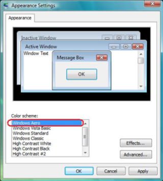
Answer:
Please refer following steps to disable «Hybrid Sleep» under Windows ® Vista™.
Step1: Please click «Control Panel». 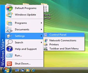
Step2: Click «System and Maintenance». 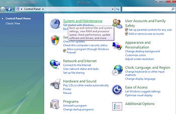
Step3: Click «Power Options» 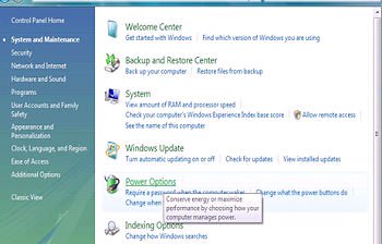
Step4: Click «Change plan settings» of «Balance» 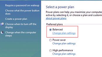
Step5: Click «Change advanced power settings. 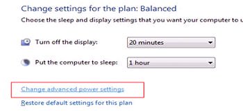
Step6: Click «sleep».
Set «Allow hybrid sleep» to off. 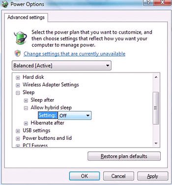
Step 7: Click OK or Apply to finish the setting.
Answer:
The problem may be caused by incorrect jumper settings or bad cables of your IDE or SATA devices. Please refer to following steps to check your system.
For IDE devices:
1.If you connect 2 IDE devices to 1 IDE cable, please double check the jumpers of your IDE devices if they were set correctly. The device which is connected to the black connector should be set as master, and the other should be set as slave (gray connector). 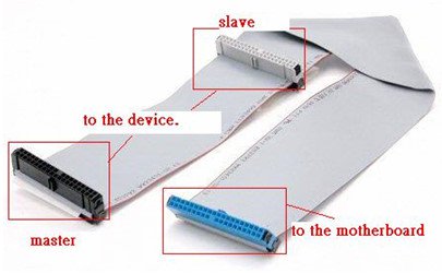
2.Please exchange the devices of master and slave on the IDE cable.
3.Please replace the IDE cable by a new one.
4.Please replace the IDE hard drive by a new one.
For SATA devices:
1.Please adjust the jumpers of your SATA2 (3.0 Gb/s) hard disk drive as SATA1 (1.5 Gb/s) mode if your motherboard supports SATA1 (1.5 Gb/s) mode only.
2.Please replace the SATA cable by a new one.
3.Please replace the SATA hard drive by a new one.
Answer:
1.If your CD is IVD12/ IVD12b (775Dual-VSTA), AV890-10 (ALiveSATA2-GLAN) or AV31/ AV31b (AM2V890-VSTA), you will get the issue.
Please execute the «Setup.exe» file from following directory of support CD.
775Dual-VISTA-> IVD12
CD\Drivers\Audio\REALTEK\MCE_XP_2K (R1.36)\
775Dual-VISTA->IVD12b
CD\Drivers\Audio/ REALTEK\MCE_XP_2K (R1.41)\
ALiveSATA2-GLAN -> AV890-10
CD\Drivers\Audio\REALTEK\MCE_XP_2K (R1.39)\
AM2V890-VSTA -> AV31/ AV31b
CD\Drivers\Audio\REALTEK\MCE_XP_2K (R1.39)\
- Right-click «My Computer» on your desktop, and click «Properties».
- Select «Hardware», and click «Device Manager».
- In «Device Manager», double-click the option «System Devices». You will find «VIA ® Standard PCI to PCIE Bridge» item with a yellow exclamation mark.
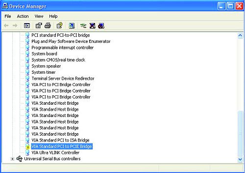
- Right-click «VIA ® Standard PCI to PCIE Bridge», and select «Uninstall». Confirm your choice by clicking «OK».
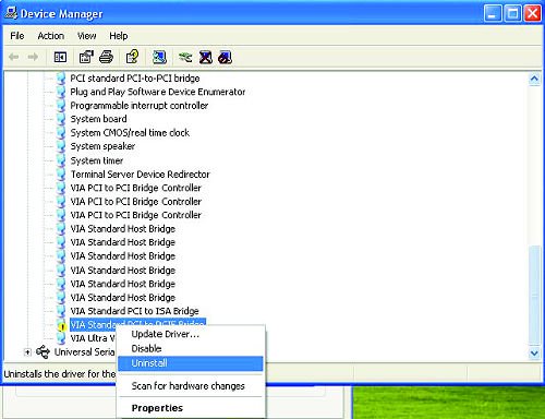
- After a few seconds, click «Scan for hardware changes» icon on the top.
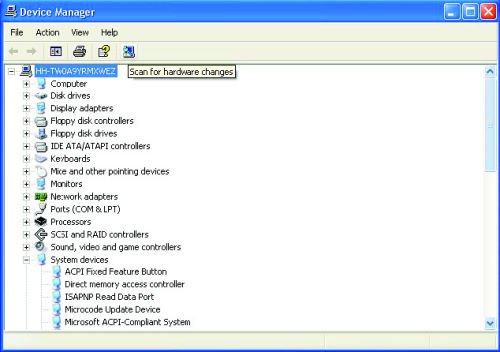
- Please set the «DRAM Frequency» as «[333MHz (DDRII 667)]» in BIOS setup if you use DDRII 667 RAM. (BIOS/ Advanced/ Chipset Configuration/ DRAM Frequency)
- Please enable the «Flexibility Option» in BIOS setup if you use DDRII 533 RAM. (BIOS/ Advanced/ Chipset Configuration/ Flexibility Option)
- If the problem still remains, please update the BIOS to P1.80 or later version.
https://www.asrock.com/mb/download.asp?Model=775Dual-VSTA#bios
- Enter «SATA Operation Mode» in BIOS setup to set the option to [RAID].
- Insert the ASRock Support CD into your optical drive to boot your system.
- During POST at the beginning of system boot-up, press key, and then a window for boot devices selection appears. Please select CDROM as the boot device.
- When you see the message on the screen, «Do you want to generate Serial ATA driver diskette [YN]?», press .
- Then you will see these messages,
Please insert a diskette into the floppy drive.
WARNING! Formatting the floppy diskette will lose ALL data in it!
Start to format and copy files [YN]?
Please insert a floppy diskette into the floppy drive, and press . - The system will start to format the floppy diskette and copy SATA drivers into the floppy diskette.
- Restart and enter «SATA Operation Mode» in BIOS setup to set the option to [AHCI].
At the beginning of Windows ® setup, press F6 to install a third-party SCSI or RAID driver. When prompted, insert a floppy disk containing the ULi ® RAID driver. After reading the floppy disk, the driver will be presented. Select the driver to install according to the mode you choose and the OS you install.
Answer:
If your board is 775VM800, please update BIOS to P1.50 or later version.
https://www.asrock.com/mb/download.asp?Model=775VM800
If your board is P4VM800, please update BIOS to P1.60 or later version.
https://www.asrock.com/mb/download.asp?Model=P4VM800
If your board is K7S41GX, Please update BIOS to P2.50 or later and VGA driver to 3.73 or later version.
https://www.asrock.com/mb/download.asp?Model=K7S41GX&s=462
If your board is K7S41, Please update BIOS to P2.30 or later and VGA driver to 3.73 or later version.
https://www.asrock.com/mb/download.asp?Model=K7S41&s=462
VGA Driver for K7S41 / K7S41GX: http://www.sis.com/download/agreement.php?id=155931
Answer:
This may be that your system was installed in IDE (or non-RAID) mode. But now it is set to RAID (AHCI) Mode. Please try to set it back to the IDE (non-RAID) mode in the BIOS>Advanced>IDE Configuration.
Here are some examples, please refer to the user manual for details.
VIA ® and Nvidia chipset:
Please set SATA Operation Mode to [non-RAID]
Please set Configure SATA as [IDE]
775Twins-HDTV (R2.0) or P4Twins-HDTV:
Please set ATA Combination Mode to [Enable]
Answer:
1. When you see the message, please type «Ctrl+C», and press «y» to terminate the program.
2 Then type «satafd». Press «enter».
3.Insert floppy disk. It will start to generate the SATA floppy disk.
Or please download the driver from ASRock Web Site and copy to floppy diskette.
https://www.asrock.com/mb/download.asp?Model=ConRoeXFire-eSATA2
Answer:
Please connect SATA hard disk to SATA1 connector and CD/DVD drive to IDE2. When you enable «ATA Combination Mode», only SATA1 and IDE2 connectors can work, other connectors are disabled. We recommend you to disable «ATA Combination Mode». In that case all 4 SATA and 2 IDE channel can work, and you can get the advantages of SATA hard disks.
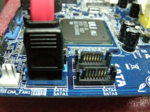
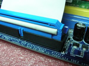
Answer:
Please press «↓» to expend the menu. The items of ICH6R are under the items of ICH7R. Please choose RAID or AHCI that correspond with the item «Configure SATA as» in BIOS settings.
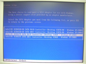
Answer:
For normal working of High Definition Audio under Windows ® XP 64bit, there is a hotfix file provided by Microsoft. Please install the hotfix before installing the audio driver. Otherwise, the audio driver may not be installed successfully.
Please click the link to download the hotfix file:
http://support.microsoft.com/?kbid=901105
Question (163): I use two SATA HDDs to create RAID 1 (mirroring) array on K8NF4G-SATA2. After I finish setting up the array and OS installation, I remove one of the two SATA HDDs. However, when I put the SATA HDD back, it shows a warning message as below when booting up the system. What should I do? 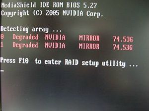 (1/16/2006)
Question: I use two SATA HDDs to create RAID 1 (mirroring) array on K8NF4G-SATA2. After I finish setting up the array and OS installation, I remove one of the two SATA HDDs. However, when I put the SATA HDD back, it shows a warning message as below when booting up the system. What should I do? (1/16/2006)
Answer:
When you remove one of the two SATA HDDs, the system will recognize the left one as an abnormal array. Then, when you put a HDD back, the system will recognize the two HDDs as two abnormal arrays. That is why it shows a warning message to remind you that is not a normal RAID 1 (mirroring) array.
In order to solve it, please press «F10» during POST to get into MediaShield Utility and do the following steps to rebuild the array.
Step 1: Please go to the MediaShield Utility (Press F10) and choose one of the SATA HDD (array) in «Array list». 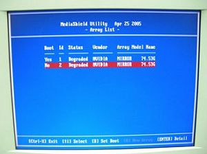
Step 2: Press «Enter» to get into the «Array Detail» 
Step 3: Press «D» to delete this array. 
Step 4: After you delete it, please go to «Array Detail» of the left Array. 
Step 5: Press «R» (Rebuild) to get into «Select From Free Disk List» 
Step 6: Press «A» then «Enter» to rebuild array. 
Step 7: Finished. 
Step 8: Press «Ctrl-X» to exit.
Answer:
Please follow below steps to update Nvidia IDE driver:
1. Under Windows ® XP, please go to «Control panel» and choose «Add/Remove program» to remove the Nvidia IDE driver.
2. Please download the new Nvidia IDE driver from https://download.asrock.com/Drivers/Special/NVIDIA_4.84IDE.zip
3. After driver download is completed, please install the new IDE driver for your system.
- Step 1: Please go to BIOS to disable the «ATA Combination Mode», or you can reserve it as default value. (BIOS/ Advanced/ IDE Configuration/ ATA Combination Mode/ Disabled)
- Step 2: Please press «F6» to install SATA drivers at the beginning of the Windows XP installation.
- Step 3: Install the SATA drivers. (Please make a SATA Driver Diskette at first. Please refer to the 775Twins-HDTV user manual page 25.)
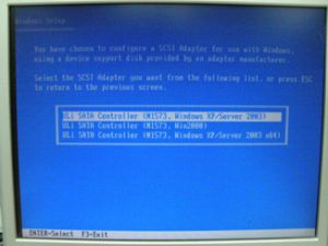
- Step 4: Start to install the operating system.
- Step 5: After finished the Windows XP installation, we recommend you to install the SATA driver from support CD.
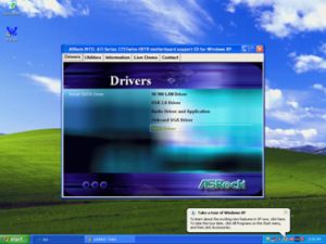
- Step 6: Now, you can start to duplicate the HDD by using GHOST program.
picture A, B. 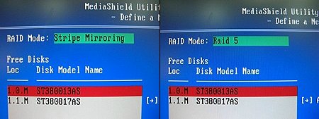
Question: I would like to use RAID functions with K8NF4G-SATA2 motherboard. When I adjust the «RAID Mode» option as «Stripe Mirroring» or «RAID 5» (picture A, B) in MediaShield Utility, the system appeared an error message «Invalid number of disks selected» (picture C, D). Why?
picture A, B.
picture C, D. 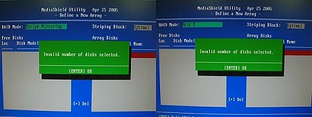 (10/17/2005)
Answer:
Please follow the below steps to install PCIE VGA card driver.
a. Please enter «Device Manager» and you will see «Standard Display Adapter (VGA) and «Standard PCI Graphics Adapter (VGA)» in the «Display Adapters» option.
b. Please Choose «Standard Display Adapter (VGA)» and right-click «Remove».
c. After removing the device, please reboot your system. Then, you will only see «Standard Display Adapter (VGA)» in «Display Adapter» option.
d. Please start to install your PCIE VGA card driver.
Question (146): I would like to install Red Hat Linux 9.0 on my VIA 8237/8237R based motherboards. But after I finished the installation of Red Hat Linux 9.0, it hung with kernel panic during boot-up. The error message is shown as below: 
How do I fix this problem?(7/15/2005)
Question: I would like to install Red Hat Linux 9.0 on my VIA 8237/8237R based motherboards. But after I finished the installation of Red Hat Linux 9.0, it hung with kernel panic during boot-up. The error message is shown as below:
How do I fix this problem?(7/15/2005)
Answer:
Please add VIA vmlinuz-2.4.20-8-IDE patch to Linux kernel by following steps.
First, copy the patched kernel (vmlinuz-2.4.20-8-ide) into floppy disk. Then, select one of the cases applies to your situation below.
(a)Clean install the Red Hat Linux 9.0.
Before exiting the installation of Red Hat Linux 9.0, press ++ to enter console mode. Then skip the case (b) to proceed.
(b)Use the kernel in existing Red Hat Linux 9.0 system.
Make sure the first boot device is CD_ROM in your system BIOS, then put the installation CD 1 into CD-ROM. When booting the installation CD, type the following command when the «boot:» message appears on the screen.
linux rescue /* press enter */ 
Then follow the instructions, and select the partition that the existing Red Hat Linux 9.0 is located in the «system to rescue» window. Then it will enter the console mode after a while.
Console mode: 
After entering the console mode, run the following commands.
# cd /mnt/sysimage /* press enter */
# mount /dev/fdo mnt /* after type this command, insert the floppy and press «enter» */ 
# cp mnt/vmlinuz-2.4.20-8-ide boot/ /* reading the floppy for a while */
# vi boot/grub/menu.lst /* press enter and it will enter /mnt/sysimage/boot/grub/menu.lst file */
Under /mnt/sysimage/boot/grub/menu.lst file press «A» to enter insert mode. 
Add the following lines into /mnt/sysimage/boot/grub/menu.lst file.
title Red Hat Linux (2.4.20-8) IDE-patched /* press enter */
root (hd0,0) /* press enter */
kernel /vmlinuz-2.4.20-8-ide ro root=LABEL=/ /* press enter */
initrd /initrd-2.4.20-8.img /* press Esc to leave insert mode */ 
Press Esc to leave insert mode and type the command below.
:w! /* press enter to save file */ 
It will appear the message «boot/grub/menu.lst» 24L, 802C 
Then, reboot system and enter the «Red Hat Linux (2.4.20-8) IDE-patched» kernel. The problem would not happen again.
Answer:
If you want to use Bypass Access Technology, the configuration of your system has to conform to the following conditions:
1.FSB 800 CPU
2.DDR 400 memory
3.BIOS version P1.10 or higher
Please refer to our website to download the BIOS.
https://www.asrock.com/mb/download.asp?Model=P4i65PE
If your configuration conforms to these conditions, please enter BIOS setup => Advanced => Chipset Configuration to enable «Bypass Access».
Answer:
The «SATA Operation Mode» provides two choices to install OS on the SATA hard disk.
There are two options for «SATA Operation Mode»: RAID (Default) and non-RAID.
a. When choosing «RAID» mode, you have to create a SATA floppy image diskette by the support CD and press «F6» to install SATA driver at the beginning of Windows XP/2000 installation.
If you want to install Windows XP/2000 on the SATA hard disk and also want to use RAID function, please set the option to «RAID».
If you want to install Windows 98SE/Me on the SATA hard disk, please set the option to «RAID».
b. When choosing «non-RAID» mode, it is not necessary to create a SATA floppy image diskette by the support CD nor press «F6» to install SATA driver at the beginning of Windows XP/2000 installation.
It is also convenient for users who do not have floppy drive.
If you want to install Windows XP/2000 on the SATA hard disk but do not want to use RAID function, please set the option to «non-RAID».
Answer:
The «SATA Operation Mode» provides two choices to install OS on the SATA hard disk.
There are two options for «SATA Operation Mode»: RAID (Default) and non-RAID.
a. When choosing «RAID» mode, you have to create a SATA floppy image diskette by the support CD and press «F6» to install SATA driver at the beginning of Windows XP/2000 installation.
If you want to install Windows XP/2000 on the SATA hard disk and also want to use RAID function, please set the option to «RAID».
If you want to install Windows 98SE/ME on the SATA hard disk, please set the option to «RAID». Please also install the latest LAN driver (3.10a or newer version) for your new system.
b. When choosing «non-RAID» mode, it is not necessary to create a SATA floppy image diskette by the support CD nor press «F6» to install SATA driver at the beginning of Windows XP/2000 installation.
It is also convenient for users who do not have floppy drive.
If you want to install Windows XP/2000 on the SATA hard disk but do not want to use RAID function, please set the option to «non-RAID».
Answer:
Please right click on the Taskbar and choose the Task Manager. In «performance» option, if you see two figures of CPU Usage History, it means that the system is working under Hyper-Threading. (Please refer to the following picture).
Hyper-Threading
If you see only one figure of CPU Usage History, it means that the system is not working under Hyper-Threading. (Please refer to the following picture). 
Non Hyper-Threading
Answer:
Due to the wrong description of «AUTORUN» program of support CD for P4i45GV, you will not see «C-Media audio driver and application» item on «AUTORUN» menu under Windows XP. Although you cannot see the item, you still can install audio driver by clicking the «Serial ATA Driver» item. The wrong versions of support CD are II33c and II33d. Please refer the following picture to install the driver from support CD.
Please click «Serial ATA Driver» item to install C-Media audio diver.
Answer:
Since the share memory uses the system memory, for better system performance, we recommend you to set share memory size to 32MB or less in the BIOS setting. (For Intel chipset based motherboards, please refer to TSD-QA-08 (June, 13th, 2003) https://www.asrock.com/support/QA/TSDQA-08.pdf)

Answer:
For Prescott CPU, some OSes (ex.NT4.0) can not be installed. In order to boot legacy OSes that cannot support CPUs with extended CPUID functions, please flash to the latest BIOS to enable «Max CPUID Value Limit» (Advanced => CPU Configuration)
We don’t provide drivers for NT4.0. If you need drivers for NT 4.0, please refer to following websites to get them.
VGA driver for P4I45GV/P4I65GV: http://downloadcenter.intel.com/
Audio driver for P4I45GV/P4I65GV: http://www.cmedia.com.tw/
Answer:
You will see these kinds of warning messages (refer to the following picture) twice during Windows XP installation.
When you see the warning messages, please select «Yes» for both.
Answer:
The table on the PCB silk screen of some boards is not correct. Please refer to the FSB Jumper Setting Table in the Quick Installation Guide bundled or in the user manual in ASRock Support CD.
K7VT4A+: Support FSB 200/266/333/400 (User Guide P.13)
Jumper Setting 200MHz: FSB_SEL0 : 1_2 、FSB_SEL2 : 1_2 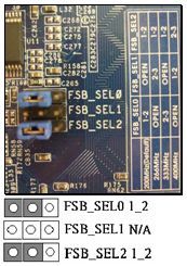
Please move the jumper cap to FSB_SEL0 : 1_2 and FSB_SEL2 : 1_2
Jumper Setting 266MHz: FSB_SEL1 : 2_3 、FSB_SEL2 : 1_2 
Please move the jumper cap to FSB_SEL1 :2_3 and FSB_SEL2 : 1_2
Jumper Setting 333 MHz:FSB_SEL0 : 2_3 、FSB_SEL2 : 1_2 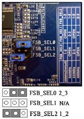
Please move the jumper cap to FSB_SEL0 : 2_3 and FSB_SEL2 : 1_2
Jumper Setting 400 MHz:FSB_SEL1 : 1_2 、FSB_SEL2 : 2_3 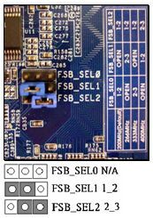
Please move the jumper cap to FSB_SEL1 : 1_2 and FSB_SEL2 : 2_3
2 seconds, it starts to work again. Why?(7/12/2004)
Answer:
If you would like to select IDE HDD in the Boot Device Priority menu, please set the IDE HDD to the first device of boot sequence in the Hard Disk Drives menu first.
AMI core 8 based BIOS would separate connected bootable devices into 3 groups, Hard Disk, Removable, and CD/DVD drives. Only first boot sequence of device in each group can be selected in the Boot Device Priority menu.
- Right-click on «My Computer» and select «Properties».
- Select the «Hardware Tab» and click on the «Device Manager» button. There should be a device section named «Processors» with a processor device.
- Right-click on the processor device, and click on «Update Driver».
- Select «Install from a list or specific location (Advanced)», and click «Next».
- Select «Don’t search, I will choose the driver to install», and click «Next».
- Click «Have Disk», «Browse. » to the installation files from support CD (E:\Drivers\CPU_DRIVER\XP\XP\English) and click «OK».
- Ignore the warning about «This driver is not digitally signed!» by clicking on «Next».
- A box will appear: «The wizard has finished installing the software for AMD Athlon(tm) 64 Processor». Click «Finish» to complete the installation.
Answer:
Please understand that this is a normal behavior of Intel boxed heat sink. The cooling fan which comes with Prescott CPU (see the following pictures) is an automatically adjustable CPU cooling fan and the speed of the fan will be adjusted according to the environment temperature. While higher temperature is detected by the INTEL boxed heat sink, the fan will speed up. So the sound will get louder.
Answer:
It might be that the CDROM is transferring in PIO mode instead of DMA mode. It is highly recommended to enable the DMA function of your IDE optical devices (CD-ROM or DVD-ROM) in order to reduce the CPU loading when accessing optical discs. Please follow the bellow procedure to enable DMA mode.
- Right click the «My computer» icon, select «Properties«. Then, select «Hardware«—-«Device Manager«.
- In «Device Manager«, select «IDE ATA/ATAPI controllers«—-double click «Secondary IDE Channel«.
- In «Secondary IDE Channel Properties«, select «Advance Settings» and adjust the «Transfer Mode» of the CDROM (Device 0) from «PIO Only» to «DMA if available«.
- Click «OK«.
- Right click the «My computer» icon, select «Properties«. Then, select «Device Manager«.
- In «Device Manager«, double click «CDROM«. Then, double click your optical device under «CDROM«.
- In the new window which displays the optical device properties, select «Settings«. Then, check the «DMA» box in «Options«.
- Click «OK«.
Answer:
Perhaps the floppy ribbon cable is connected to the floppy drive with the wrong orientation. Please reconnect the floppy cable and make sure to match the red marking on the floppy ribbon cable with Pin1 of the floppy drive connector. However, some floppy drives’ connectors may not be easily to define Pin1. You can try to check around the connector. Usually, there will be labels for Pin1 or Pin2.
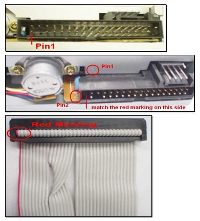
Answer:
Actually you will see these kinds of warning messages (refer to the following picture) twice during Windows XP installation.
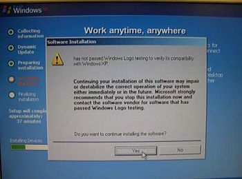
When you see the warning messages, please both select «Yes». However, if you still need the Microsoft certificated SATA driver, it is available at https://www.asrock.com/mb/download.asp?Model=K7S8XE%2b . Please download the driver and save it in a floppy disk before Windows installation.
Answer:
Please read below operation guide of Serial ATA HDD Hot-Plug on ASRock motherboard carefully.
Before you process the SATA HDD Hot-Plug, please check below cable accessories from the motherboard gift box pack.
7-pin SATA data cable x 2
SATA power cable with SATA 15-pin power connector interface x 1
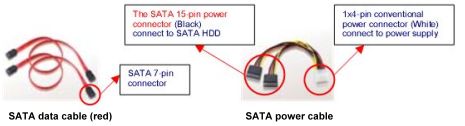
1.Without SATA 15-pin power connector interface, the Serial ATA HDD Hot-Plug cannot be processed.
2.Even some SATA HDDs provide both SATA 15pin power connector and IDE 1×4-pin conventional power connector interfaces, the IDE 1×4-pin conventional power connector interface is definitely not able to support Hot-Plug and will cause the HDD damage and data loss.
- Below operation procedure is designed only for ASRock motherboard, which supports SATA HDD Hot-Plug.
*SATA Hot-Plug support of ASRock motherboard is indicated in the product spec on our web site . - Make sure your SATA HDD can support hot-plug function from your dealer or HDD user manual. The SATA HDD, which cannot support hot-plug function, will be damaged under the hot-plug operation.
- Please make sure the SATA driver is installed into system properly.
The latest SATA driver is available on our support web site https://www.asrock.com/support/index.asp - Make sure to use the SATA power cable & data cable, which are from ASRock motherboard package.
- Please follow below instructions step by step to reduce the risk of HDD crash or data loss.
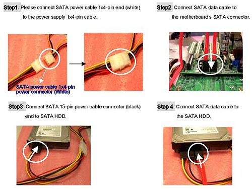
How to Hot-Unplug a SATA HDD:
Points of Attention – Before you process the Hot-Unplug:
Please do follow below instruction sequence to process the Hot-unplug, improper unplug procedure will cause the SATA HDD damage and data loss.
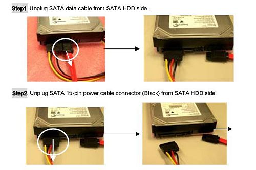
Answer:
When installing Linux which the Kernel version is order than 2.4.21 on P4AL-8X or P4AL-800, please follow the bellow procedure.
- When installing Linux, at the page choosing the installation between «Graphic mode» or «Text mode», please type » boot: linux pci=conf2 » to complete the installation.
- After the installation, in the GRUB boot up menu, please press «a» to modify the kernel argument. Please type » ro root=LABEL=/ pci=conf2 » in order to boot up correctly.
- Download the latest Kernel from http://www.kernel.org/pub/linux/kernel/ , for example, linux-2.4.22.tar.gz from another system.
- Copy the latest Kernel into this Linux system.
- Compile the latest Kernel.
Answer:
Please unplug the ATX power and remove the battery, use a metal material like paper clip to short the CLRCMOS1 soldering points or CLRCMOS2 jumpers for 3 seconds. After that, install the battery and plug the ATX power back to the motherboard.
Note: Please do not clear the CMOS right after you update the BIOS.
Answer:
According Intel DVMT (Dynamic Video Memory Technology,) the amount of video memory is dependent upon the amount of pre-allocated memory set for your system. It allocates memory based on system requirement and is not configured by user. Memory can be adjusted up to the maximum limit set by the graphics driver.
Please refer Intel web site for detail information:
http://support.intel.com/support/graphics/gaming/video.htm
Answer:
For Intel CPU: You do not need to do any setting. When you install CPU at the first time, all that you need to do is go to BIOS and «Load setup defaults», then the system will auto detect the correct CPU FSB.
For K7VT2 and K7VM2: There is a FSB_SEL jumper on the motherboard .
FSB 100Mhz set 2-3
FSB 133Mhz set 1-2
Answer:
Since Microsoft is only developing drivers for Windows XP and 2000, you will have to use a 3rd party vendor’s drivers. Also Power Management for USB 2.0 works fine under Windows XP. It may not work properly under Win98/ME/2000. Please check detailed information from Microsoft Web Site:
Answer:
Please install the LAN driver manually under Windows 98/ME/2000/XP with the following steps:
1. Put the K7VT2 support CD into the CD-ROM drive.
2. Double click on the «My Computer» icon, then right click on the CD-ROM drive and browse the support CD.
3. Locate the «winsetup.exe» on \Drivers\LAN folder and double click on «winsetup.exe» to run LAN installation program.
4. After 20 seconds, «The installation is completed!» will appear then you have finished the LAN installation.
5. Please restart your computer.
Answer:
STEP 1:
4 CH: Connect the front L/R channel to «Line Out», the rear L/R channel to «Line In».
6 CH: Connect the front L/R channel to «Line Out», the rear L/R channel to «Line In», and the Center/Subwoofer channel to «Mic In».
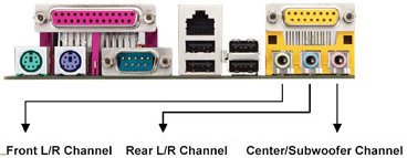
STEP 2:
After installation of C-Media Audio driver, you will find an icon «C-Media Audio configuration» on the taskbar.
STEP 3:
Click the icon, and the screen will show the current audio configuration.
Select «Output» to change your audio configuration. Select «Analog» for Output Type and choose «4 channels» / «6 channels» for your speaker configuration.
Then press «Apply» and press «Ok».
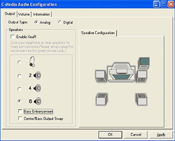
Answer:
First, The OS (for example Windows series) should be able to support 48-bit LBA mode that enables the system to run and manipulate big drive, namely, only Windows 2000 and Windows XP could achieve this goal.
ASRock H110M-HDV Intel ME Driver
Разработчик: Intel 
- Currently nan/5
Rating: nan/5 (Total Votes: 0)
— ASRock Супер сплав
— Поддержка 6-го поколения Intel Core процессоры (Socket 1151)
— Поддержка двухканальной DDR4 2 133
— 1 PCIe 3.0 x16, PCIe 2.0 2 x1
— Графика Параметры вывода: D-Sub, DVI-D, HDMI
— 7.1 CH HD Audio (Realtek ALC887 Audio Codec), ELNA Аудио Шапки
— 4 SATA3
— 4 порта USB 3.0 (2 спереди, 2 сзади)
— Поддерживает полную Защита от скачков, ASRock Live Update & APP Магазин
Обо мне Драйверы:
Функция управления двигателем позволяет компьютерам, чтобы сделать использование различных технологий, таких как АМТ или управления питанием. Установка соответствующих драйверов позволяет совместимые системы извлечь выгоду из этой функции встроенного в чипсет процессора.
После обновления этого программного обеспечения на более новую версию, вы получите различные улучшения стабильности повышенную совместимость с различными компонентами, и даже добавлена поддержка новых технологий.
Чтобы извлечь выгоду из всего этого, убедитесь, что загрузка запись удобна для характеристик системы, получить пакет, запустить программу установки и следуйте инструкциям на экране для завершения установки. Кроме того, дон и Rsquo; забудьте выполнить перезагрузку, чтобы все изменения вступили в силу.
Имейте в виду, что, даже если другие платформы, возможно, быть совместимым, а также, мы не рекомендуем использовать этот выпуск на других, чем те, выделенных операционных систем.
Это, как говорится, если вы намерены применить это ME освободить, нажмите кнопку скачать и установить пакет. Дон & Rsquo; забудьте проверить обратно с нашего сайта как можно чаще, так что вы не & Rsquo;. Не пропустите ни одного нового выпуска