How to power your PC via schedule – Enabling Auto-Power-On on your PC
In this guide, we’re going to go over how to enable Auto-Power-On on the Beelink GK35 mini PC. This process can likely broadly apply to other computers as well.
Automation – it’s a wonderful thing! Through the magic of scheduling and passive “listening”, it is possible to cut out a good chunk of the busywork that would otherwise take up valuable time from your day.
This extends to even the simple act of turning on a computer! Thanks to a handy feature called auto-power-on, it’s possible to schedule your PC to turn itself on without human intervention. This is excellent for those who use their PC at similar times each day, and want it to be ready for them in advance.
How do I enable Auto-Power-On
FIRST, before doing anything. You’ll need to make sure that Fast Startup is disabled. Fast-startup is a Windows power settings option that increase the speed at which the computer powers on.
How to disable Fast Startup in Windows 10
In the age of M.2 NVMe SSDs however, where boot speeds are already extremely fast, the speed gain is negligible, and it ultimately causes more problems than it fixes. In this case, it can hinder auto-power-on and other automation functions from working outright.
To disable fast startup, first open the control panel and select power options. This can be done by searching for the control panel in the Start menu search bar, then selecting the icon with the green battery. (If you can’t see, change the “View by” to “large icons”.

Next, select “choose what the power buttons do”.

You will then need to uncheck “turn on fast startup” if it is enabled. If the option is greyed out, click the “change settings that are currently unavailable” to fix this.

Now that you’ve disabled fast startup, you can begin to enable auto-power on.
How to access the BIOS
Enter the BIOS for the system. There’s two ways to do this:
- Press ESC, DEL, or other keys as defined by your system during the initial booting of the PC (in the case of the GK35, when you see the Beelink logo).
- Access it through Windows’ Advanced Startup Options.
Because we’re already in Windows at this point, it will be quicker to do it via the latter.
In the Windows start menu, select the power button, then select restart while holding the LEFT SHIFT key.,

This will bring you into the Advanced Startup options.
From here, select Troubleshoot, Advanced Options, then finally UEFI Firmware Settings. This will reboot the PC straight into the BIOS.
Enabling Auto-Power-On (RTC Wake)
You can navigate the BIOS via the arrow, enter and escape keys on your keyboard.

Press the right arrow key to move to the advanced tab.
From the list of items, select S5 RTC Wake Settings.

Finally, select the Wake Up System from S5 option and set it to either Fixed Time or Dynamic Time.
- Fixed Time allows you to set a specific time (24-hour Clock Format) for the system to power on. Some computers can support more granite scheduling (i..e, specific days of the week).
- Dynamic Time allows you to make the system automatically power on after a certain period of time has elapsed after it is powered off. For the GK35, you can set this interval to be anywhere from 1 to 5 minutes.
Select whichever type of auto-wake you’re happy with, and then press the escape key.

Navigate to the Save & Exit tab, then click Save Changes and Exit to exit the BIOS and go back to Windows.

Now whenever your PC is next powered off, it will automatically turn itself on at the time defined by you!
What is the “S5” power option?
Enabling auto-power on may not initially be as straightforward as you’d like. The Aptio Setup Utility that acts as the BIOS for most mini PC’s can be a harsh, archaic environment full of confusing technical terminology.
In the GK35, the option for auto-power-on is under the “S5 RTC Wake Settings” menu item.
To break it down into easily digestible components:
- “S5” refers to the System Power State. Modern computers can have their power state categorized into 7 distinct stages.
- S0 = The computer is on.
- S1-S3 = The computer is asleep. The higher the number, the deeper the sleep and the lower the power consumption. Deeper sleeps will take longer to wake from.
- S4 = The computer is in hibernation. This is lowest possible point of power consumption without the device being outright turned off. Most useful on mobile devices like laptops.
- S5 = The system is turned off, except for a small trickle of electricity to components such as the power button and ambient LED lights.
- G3 = The system is completely off. No electricity, etc. Not commonly found in consumer computers.
For more about System Power States, check out the official Microsoft documentation.
4 s5 rtc wake settings, 1 s5 rtc wake settings, 2 wake system with fixed time – Kontron CP3002 uEFI User Manual
Page 17: 3 wake system with dynamic time, S5 rtc wake settings, Wake system with fixed time, Wake-up hour, wake-up minute, wake-up second, Wake system with dynamic time, Cp3002/-rc/-ra uefi bios main setup

CP3002/-RC/-RA uEFI BIOS
ID 1042-8946, Rev. 3.0
P R E L I M I N A R Y
S5 RTC Wake Settings
This screen provides functions for specifying the S5 RTC Wake Settings.
S5 RTC Wake Settings
This function defines the RTC wake-up settings to allow the system to wake up from the S5
(soft off) state.Wake System with Fixed Time
This function allows the system to wake up from S5 state at a specified time.
Default setting: Disabled
Wake-Up Hour, Wake-Up Minute, Wake-Up Second
This function is used to specify the hour (0-23), the minute (0-59) and the second (0-59) when
the system is to wake up from S5 state.This function is available only when the function “Wake System with Fixed Time” is
set to Enabled.Wake System with Dynamic Time
This function is intended for debugging purposes only and is therefore locked.
A p t i o S e t u p U t i l i t y — C o p y r i g h t ( C ) 2 0 0 9 A m e r i c a n M e g a t r e n d s , I n c .
ONN Laptop BIOS Exploration

I recently acquired an ONN Laptop. This is a brand of laptop sold exclusively through Walmart in the US.
I decided to investigate this laptop because I had a suspicion it’s BIOS was not particularly locked down. Turns out my suspicion was well founded; this article will describe the various configuration settings made available through BIOS on the ONN Laptop.
I was unable to conduct extensive vulnerability testing with this laptop as by setting a particular BIOS option, through the built-in BIOS Configuration Utility nonetheless, I bricked the laptop. Read the analysis section for more information, where I also list out the various attacker vectors I identified.
Analysis
Through the configuration menus listed below it is possible to enable Intel DCI without making any custom modifications to the BIOS image using a tool such as RU.efi . This means it is possible to enable Intel DCI without disabling and re-enabling Secure Boot. I was able to connect the laptop to a host system running Intel System Debugger (legacy) and successfully halt the laptop’s processor and see the system state, as well as perform some rudimentary debugging at this level.
The interesting functions of the BIOS — specifically the network enabled capabilities, do not seem to function properly. Every time I tried setting a boot URI in the UEFI HTTP IPv4 configuration menu, the option value reset to blank every time I saved the BIOS configuration.
Several other options, such as ASF Support in Advanced / AMT Configuration also displayed this behavior. When I set ASF Support to enabled, saved, and then exited the BIOS, on the very next entry into BIOS the ASF Support option was set to disabled.
I was able to get the WiFi configuration to successfully authenticate to the WiFi network, but the device never responded to ICMP or other IP level messages. It seems like there is some Layer 2 attack surface here in terms of authenticating to the WiFi access point, which may be the only “remote” attack vector. This still would require local proximity to the device.
Other interesting input includes the Cert Enrollment option in the Advanced / TLS Configuration menu. This allows certificates to be loaded from USB storage, which invites some unique opportunities, given physical access.
There of course are the UEFI NVRAM variables as potential vectors to supply malicious input. I did not explore this avenue beyond setting options in the BIOS configuration utility.
Also worth noting is that the Firmware Configuration Menu contains an option for Ignore Policy Update — when I set this to be the configured option, the laptop would no longer boot, not even to BIOS, resulting in a bricked laptop. It looks like the BIOS manufacturer attempted to warn users about setting this option, but it was not clear to me that setting this option as the configured value would have the effect of bricking the laptop.
I might have been able to restore the laptop to a functional state if I had made a back up of the SPI ROM prior to testing; I did not do this, foolishly not thinking that there could be any way to permanently brick the laptop through BIOS shy of powering off the device during a firmware update. Certainly I did not anticipate a configurable option placing the laptop in such a state.
The best advice I can offer users of this laptop is that they set the User Password under the Security Menu — this will require a password to POST as well as access BIOS settings. I’m not convinced that there isn’t a way to bypass this authentication mechanism, but it is better than nothing. Like most devices, physical access to this device essentially means game over in terms of security — by allowing debug capabilities it is possible to manipulate the laptop at the platform level.
Below is a run through of the BIOS Configuration Utility menus. Note that except for one or two special instances, the values in the images for the various settings are the default values.
Main Menu
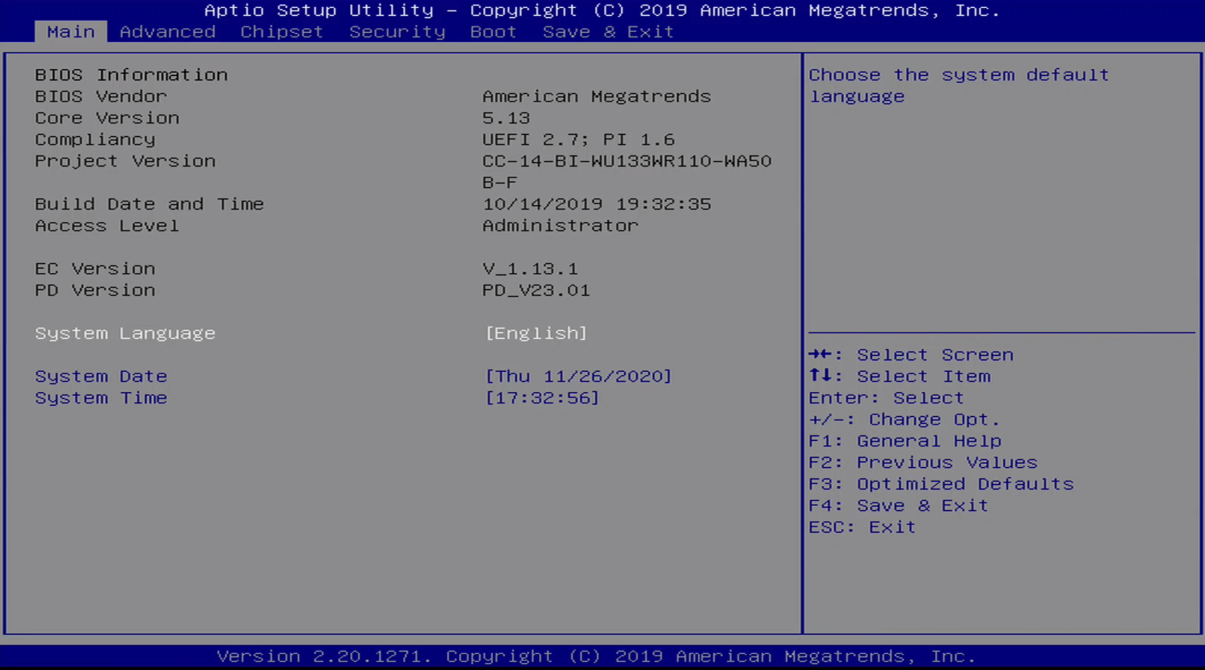
This is the first screen the user is greeted with upon entering system BIOS. The user can enter the system BIOS by pressing the Delete button at the ONN splash screen. It contains version information for the currently install BIOS image.
There are six total menus:
- Main
- Advanced
- Chipset
- Security
- Boot
- Save & Exit
Advanced Menu
The advanced menu is where most BIOS configuration options are set. This includes the following sub-menus:
- RC ACPI Settings
- Connectivity Settings
- CPU Configuration
- PCH-FW Configuration
- Thermal Configuration
- Platform Settings
- ACPI D3Cold Settings
- Overclocking PErformance Menu
- AMT Configuration
- Intel ICC
- Thunderbolt(TM) Configuration
- Debug Settings
- Trusted Computing
- ACPI Settings
- SMART Settings
- S5 RTC Wake Settings
- Serial Port Console Redirection
- Intel TXT Information
- Acoustic Management Configuration
- Switchable Graphics
- AMI Graphic Output Protocol Policy
- SIO Configuration (Non-functional)
- PCI Subsystem Settings
- USB Configuration
- CSM Configuration
- NVMe Configuration
There are a few additional Networking menus that appear once Network Stack is enabled and the BIOS settings have been saved and the system reset. Those are:
- Wi-Fi Configuration
- VLAN Configuration
- MAC:<MACADDRESS>-IPv4 Network Configuration
- MAC:<MACADDRESS>-HTTP Boot Configuration
- MAC:<MACADDRESS>-IPv6 Network Configuration
We will explore these last five menus near the end of this post.
Advanced / RC ACPI Settings
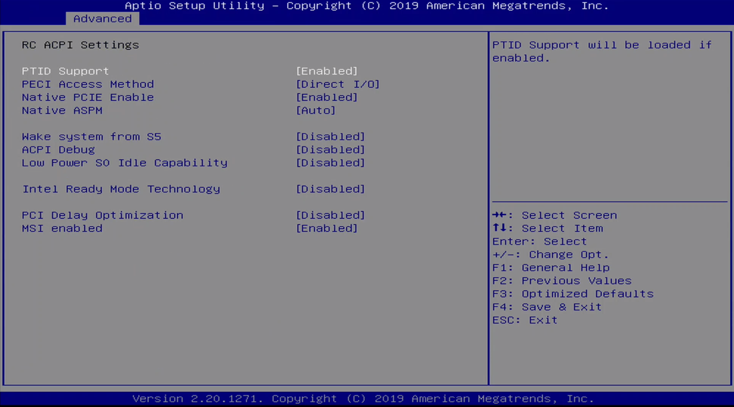
This seems to be a power management and monitoring subsystem of the chipset. It contains a number of sub-menus:
- PTID Support
- PECI Access Method
- Native PCIE Enable
Lower Power SO Idle Capability
Intel Ready Mode Technology
Advanced / Connectivty Menu
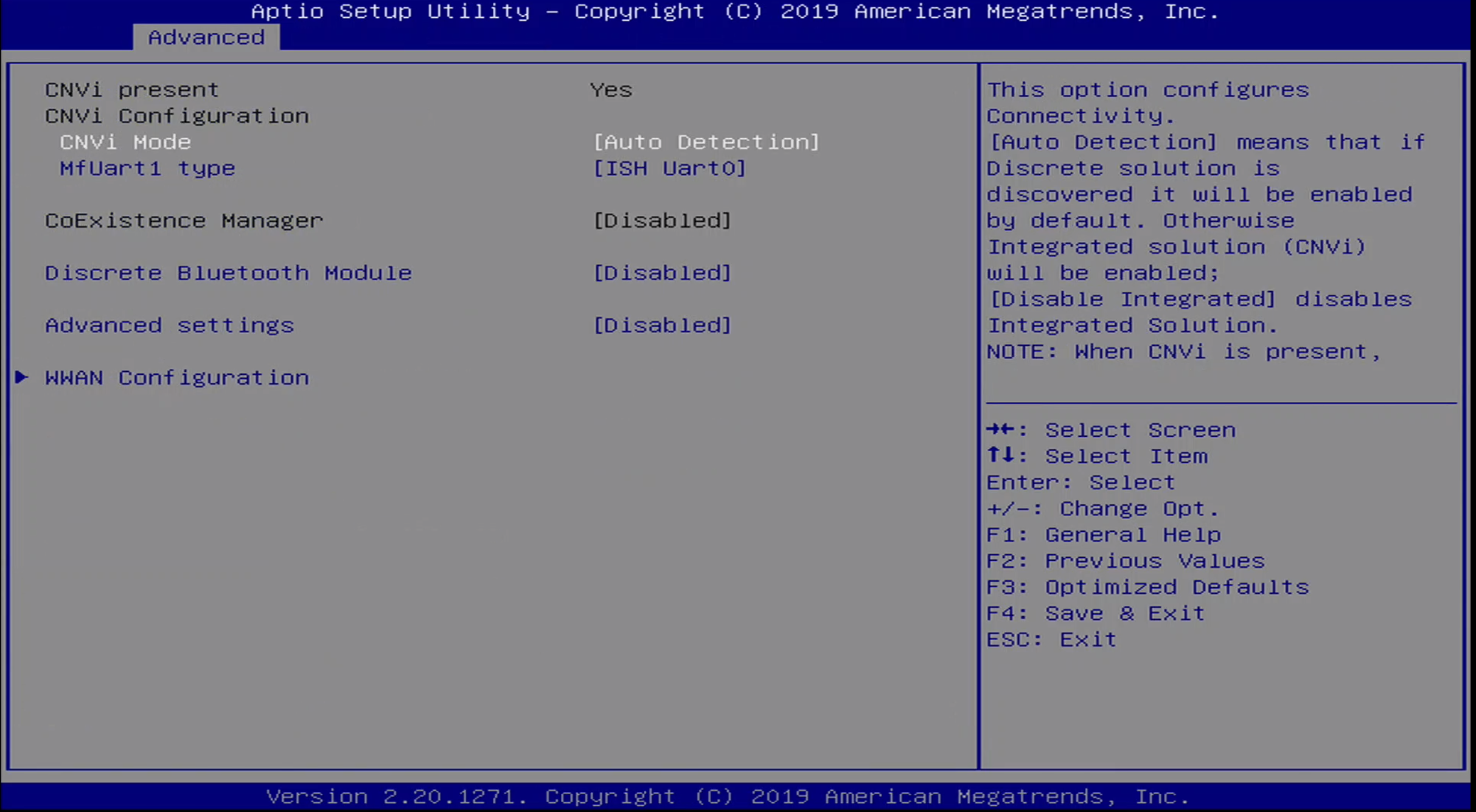
The Advanced / Connectivity Menu is used to configure onboard chip detection for communications chips, such as Bluetooth and WWAN.
Advanced / CPU Configuration Menu
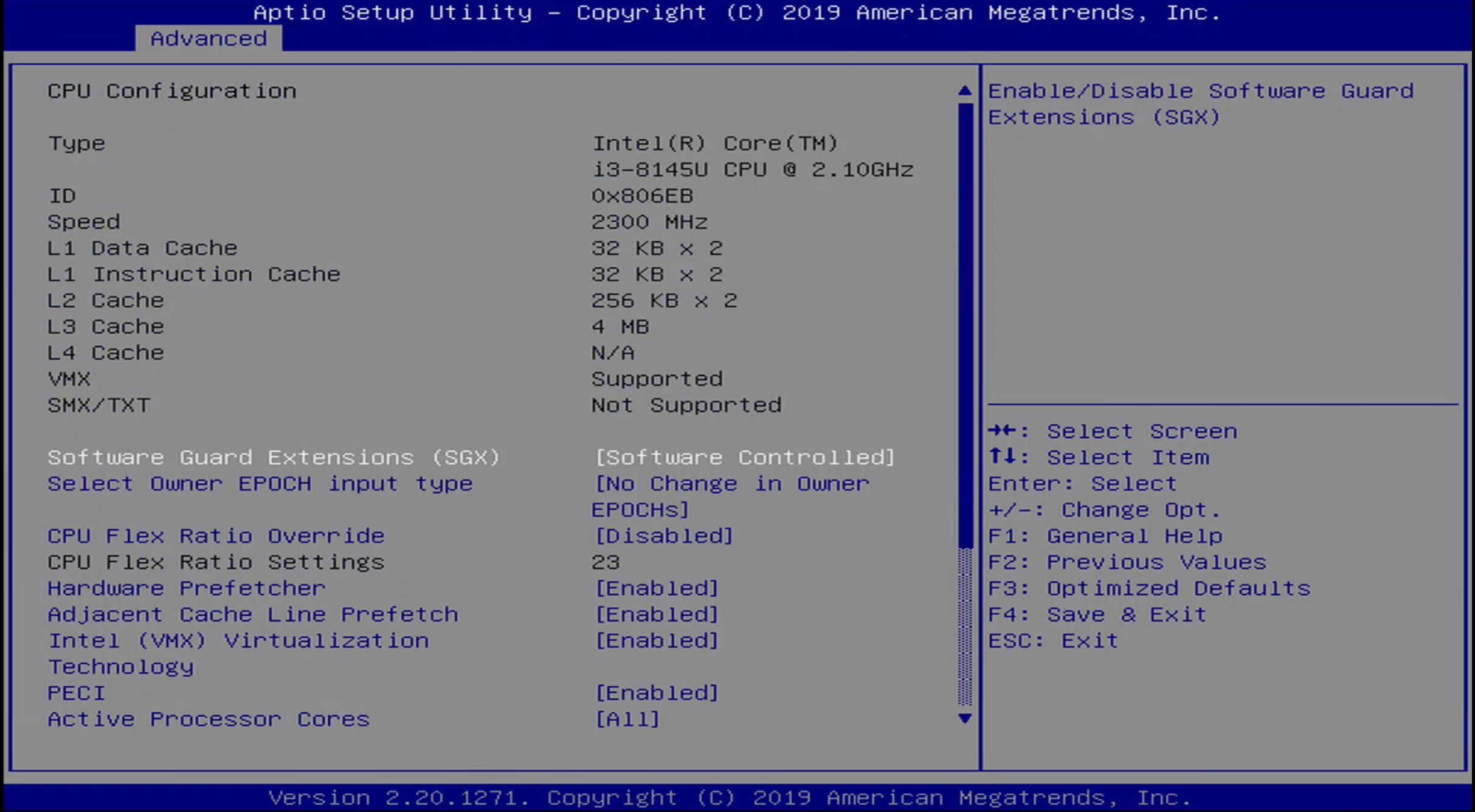
The Advanced / CPU Configuration menu details the L1-L4 cache information, as well as the processor ID and speed. Additioanlly, virtualization can be configured through this menu.
Advanced / Power & Performance Menu
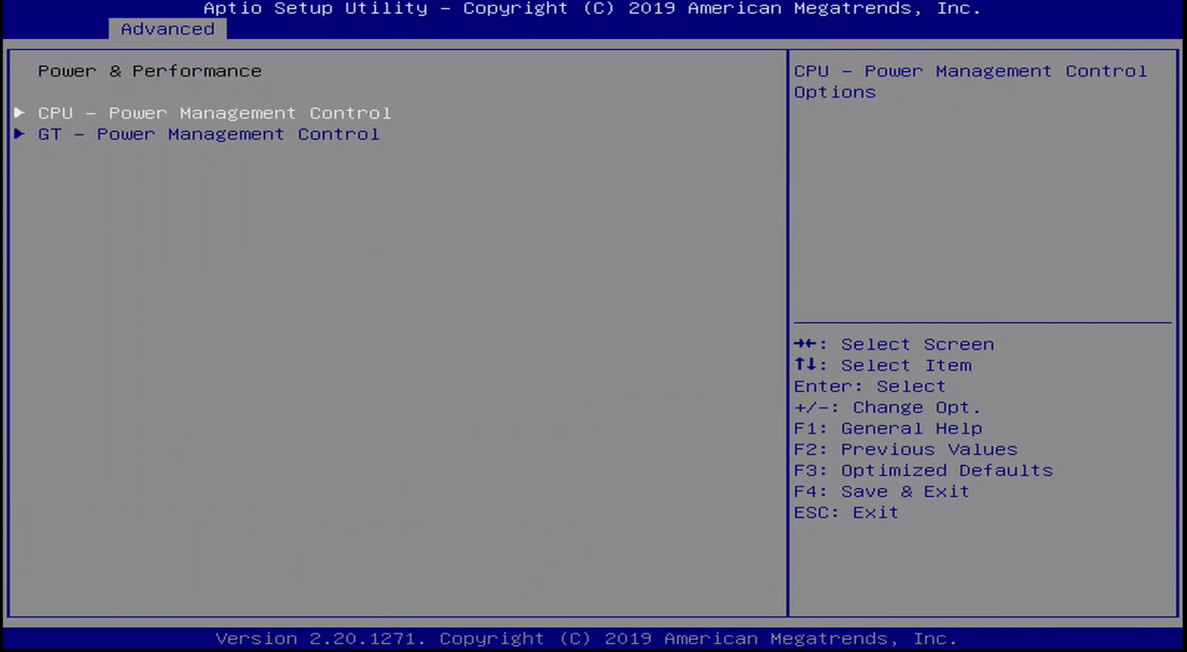
The Power & Performance Menu allows the user to configure CPU and GT power options.
Advanced / PCH Menu
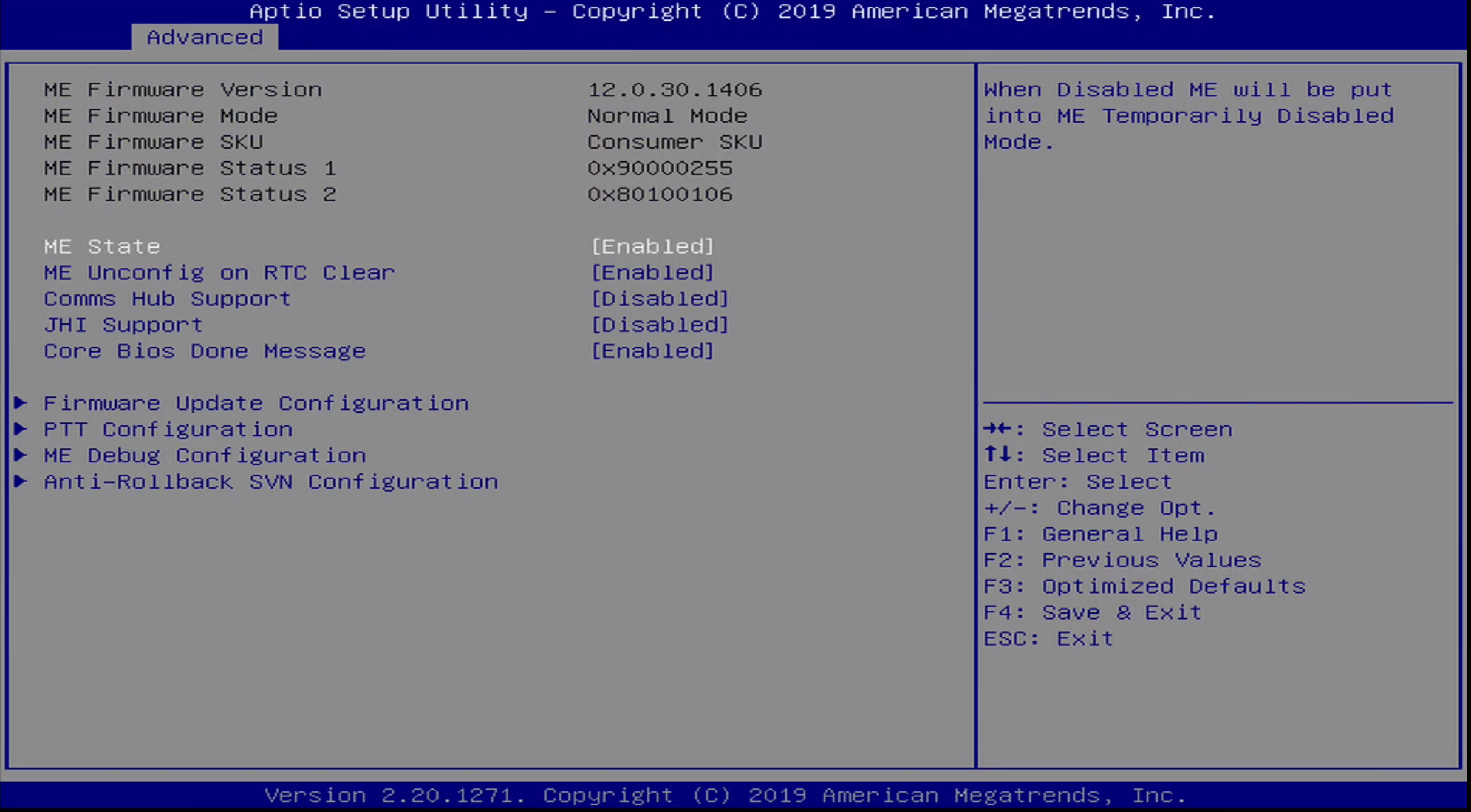
The PCH Menu includes information on Intel ME, including version information. It allows various ME options to be set, including ME debug options.
Advanced / PCH Menu / ME Debug Settings
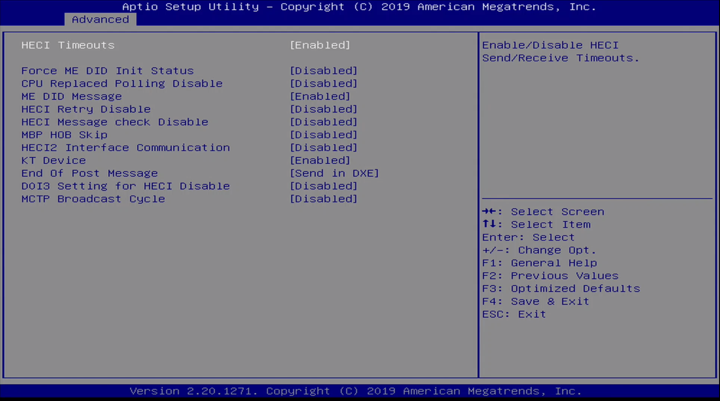
These are options for debugging Intel Management Engine. They include:
- HECI Timeouts
- Force ME DID Init Status
- CPU Replaced Polling Disable
- ME DID Message
- HECI Retry Disable
- HECI Message check Disable
- MBP HOB Skip
- HECI2 Interface Communication
- KT Device
- End of Post Message
- DOI3 Setting for HECI Disable
- MCTP Broadcast Cycle
Advanced / Thermal Configuration Menu
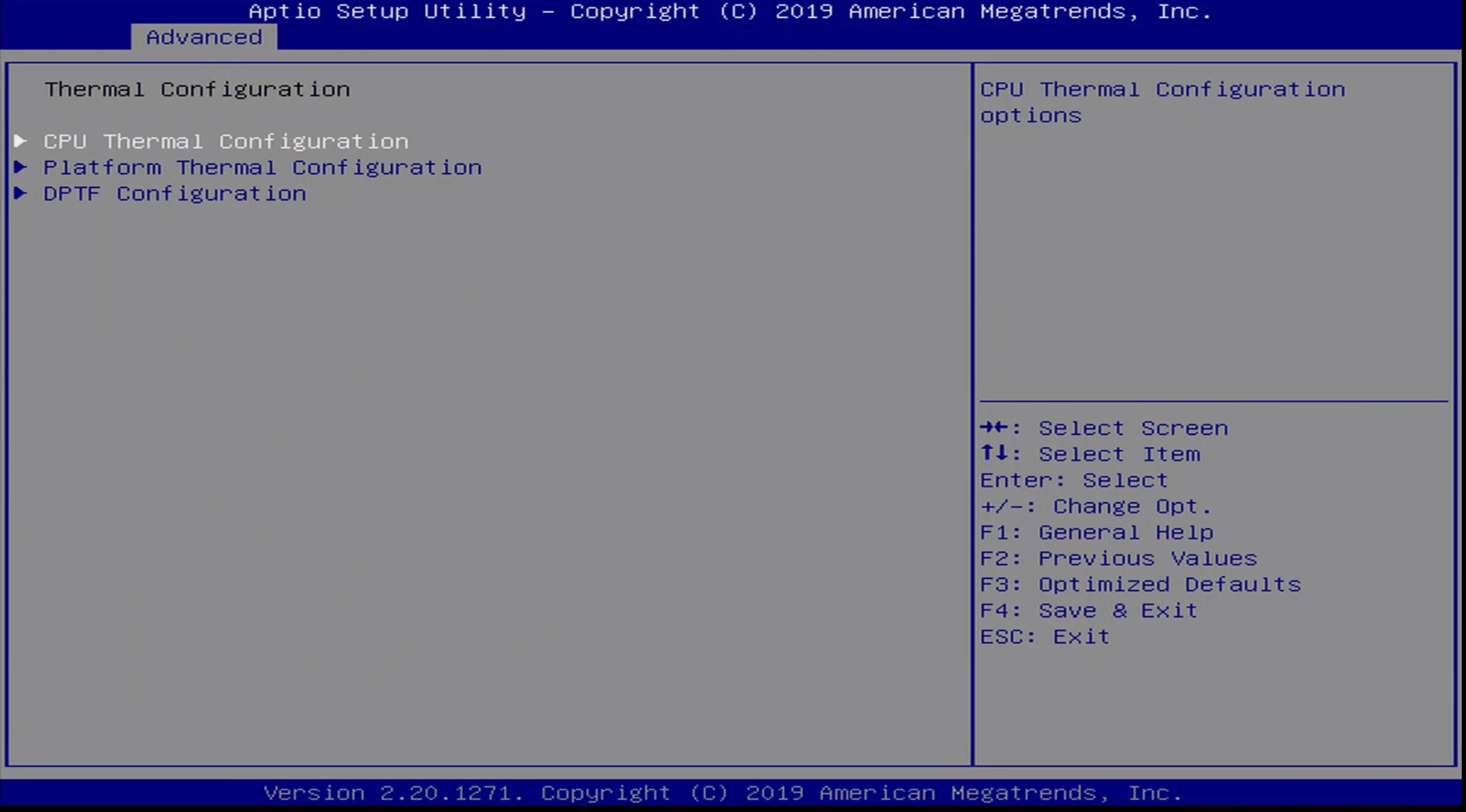
The Advanced / Thermal Configuration Menu allows thermal configuration of CPU, Platform, and DPTF.
Advanced / Platform Settings Menu
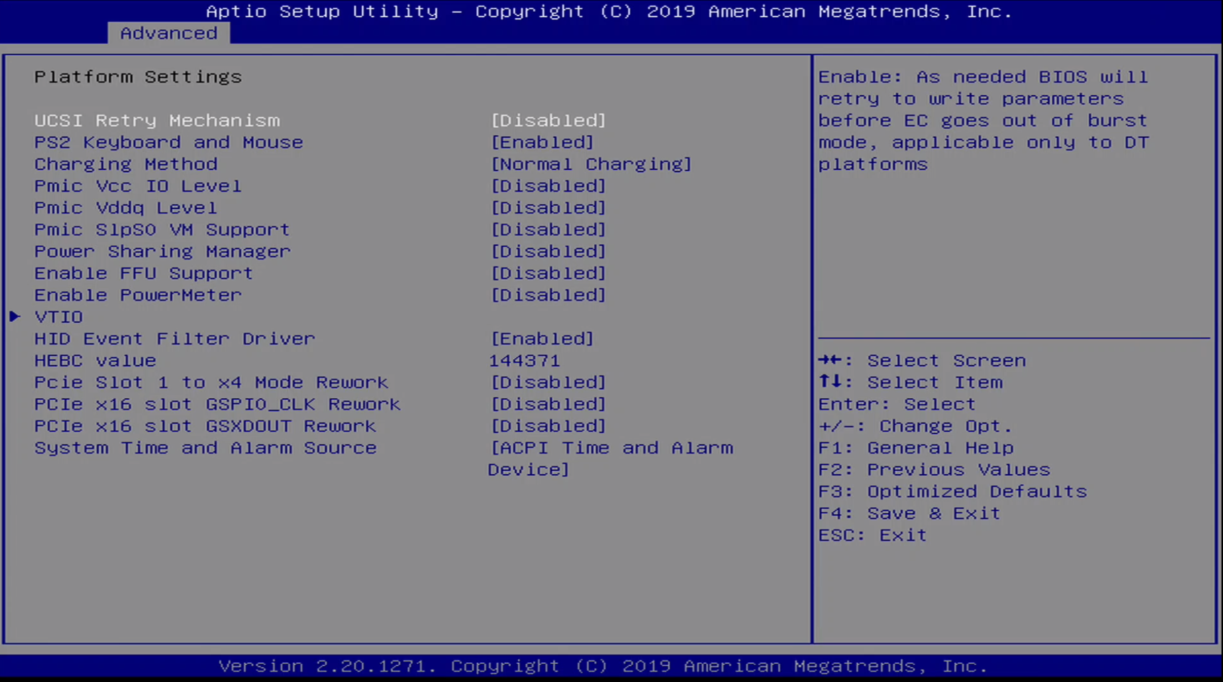
The Advanced / Platform Settings Menu contains the following options:
- UCSI Retry Mechanism
- PS2 Keyboard and Mouse
- Charging Method
- Pmic Vcc IO Level
- Pmic Vddq Level
- Power Sharing Manager
- Enable FFU Support
- Enable PowerMeter
- VTIO
- HID Event Filter Driver
- HEBC value
- Pcie Slot 1 to x4 Mode Rework
- PCIe x16 slot GSPIO_CLK Rework
- PCIe x16 slot GSXDOUT Rework
- System Time and Alarma Source
Advanced / D3Cold Settings Menu
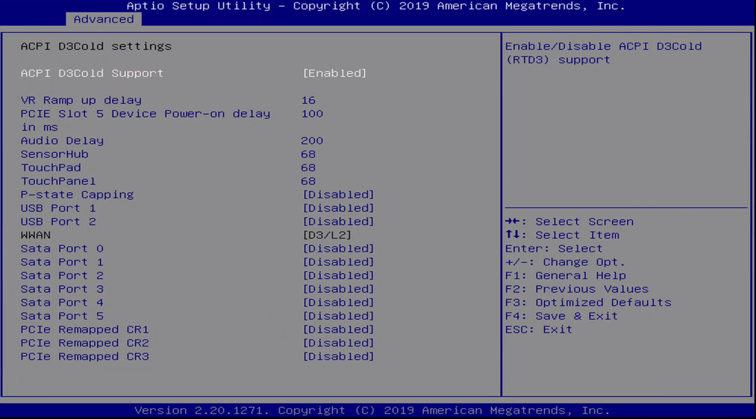
The Advanced / D3 Cold Settings Menu includes the following options:
- ACPI D3Cold Support
- VR Ramp up delay
- PCIE Slot 5 Device Power-on delay in MS
- Audio Delay
- SensorHub
- TouchPad
- TouchPanel
- P-state Capping
- USB Port 1
- USB Port 2
- WWAN
- Sata Port 0
- Sata Port 1
- Sata Port 2
- Sata Port 3
- Sata Port 4
- Sata Port 5
- PCIe Remapped CR1
- PCIe Remapped CR2
- PCIe Remapped CR3
Advanced / Overclocking Configuration Menu
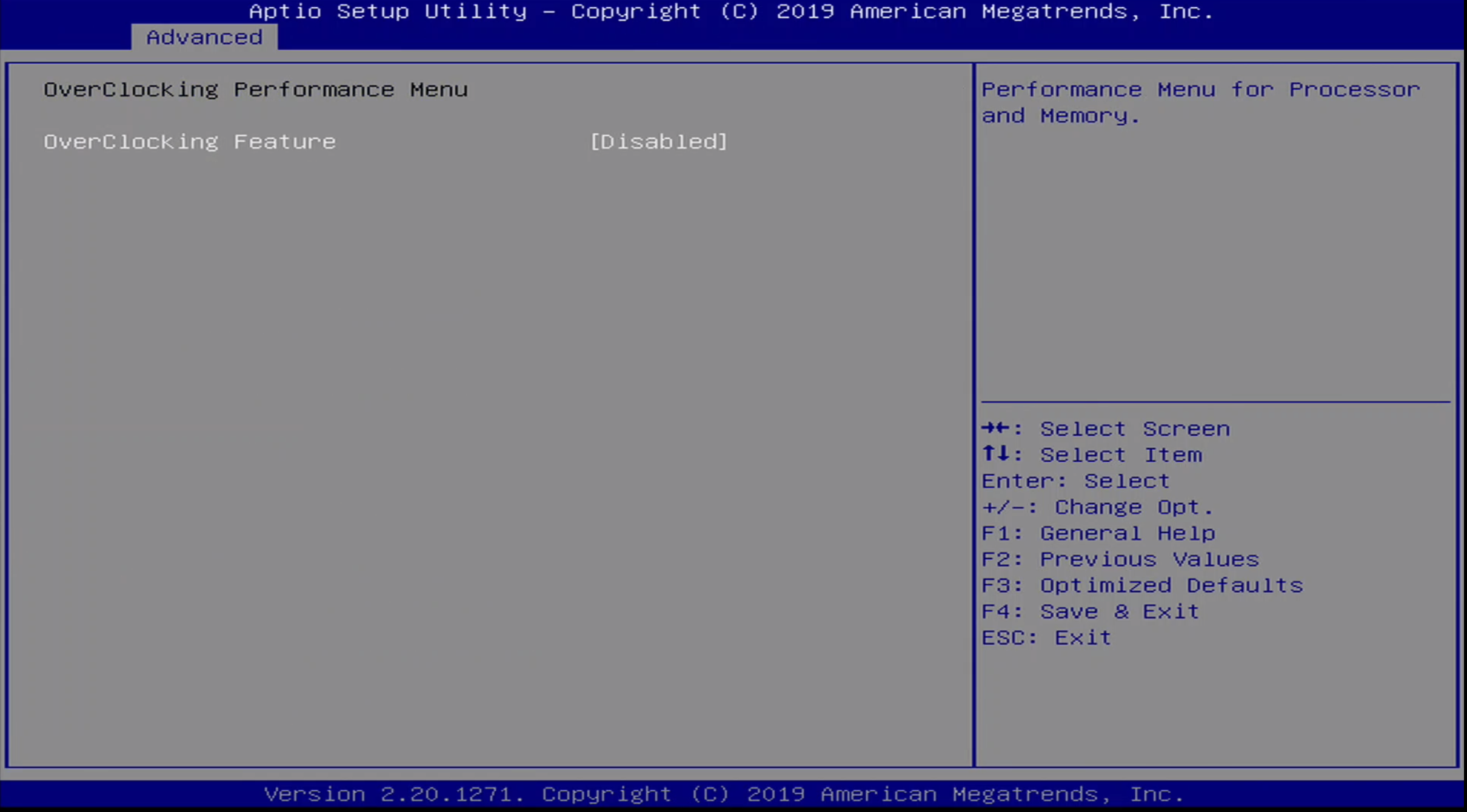
The Advanced / Overclocking Menu allows the ability to enable/disable overclocking on the platform.
Advanced / Intel AMT Menu
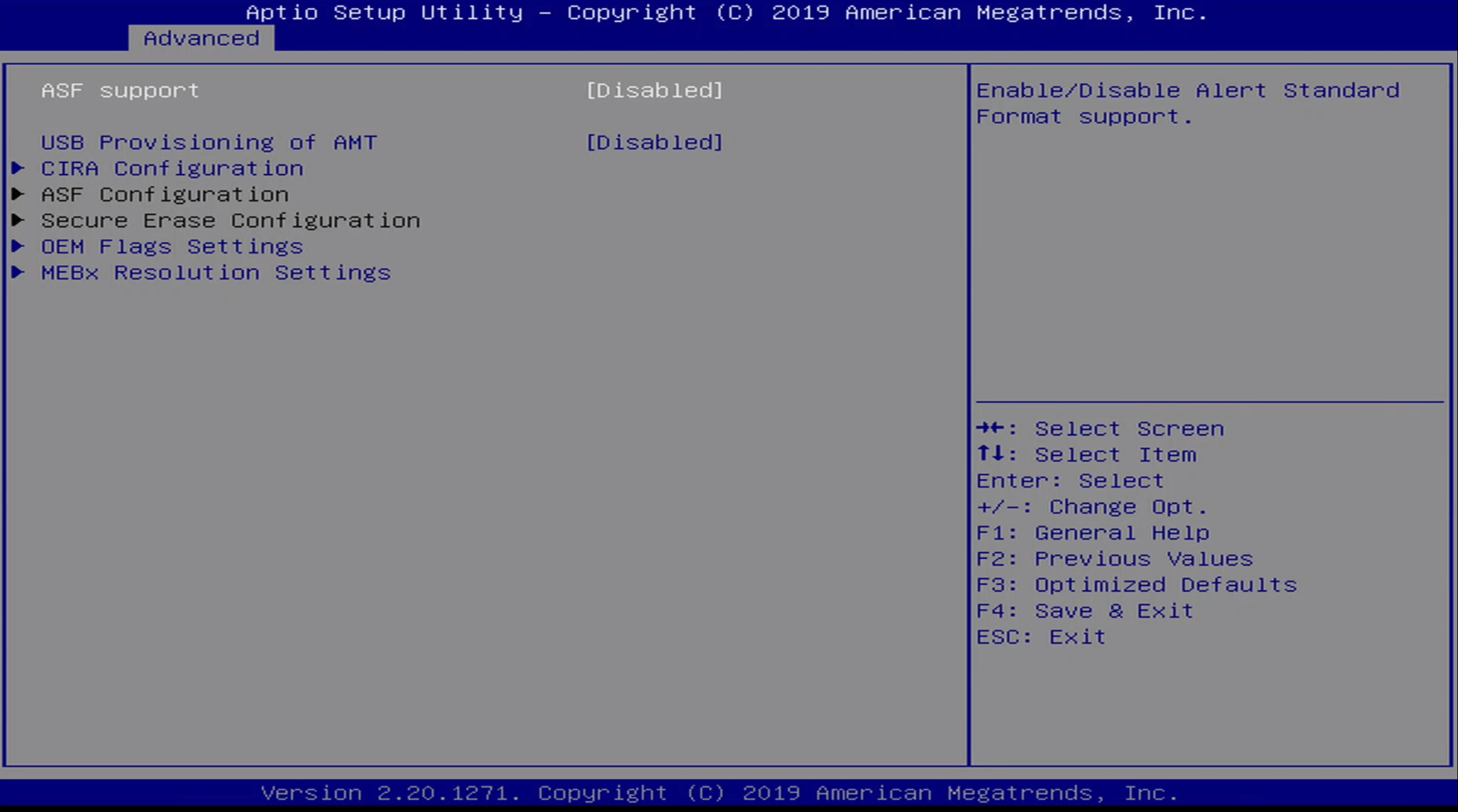
The Advanced / Intel AMT Menu contains configuration options for Intel Active Management Technology. We will explore this capability further in the analysis section of this post.
The configuration options for this menu include:
- ASF Support
- USB Provisioning of AMT
- CIRA Configuration
- ASF Configuration
- Secure Erase Configuration
- OEM Flags Settings
- MEBx Resolution Settings
Advanced / Intel ICC Menu
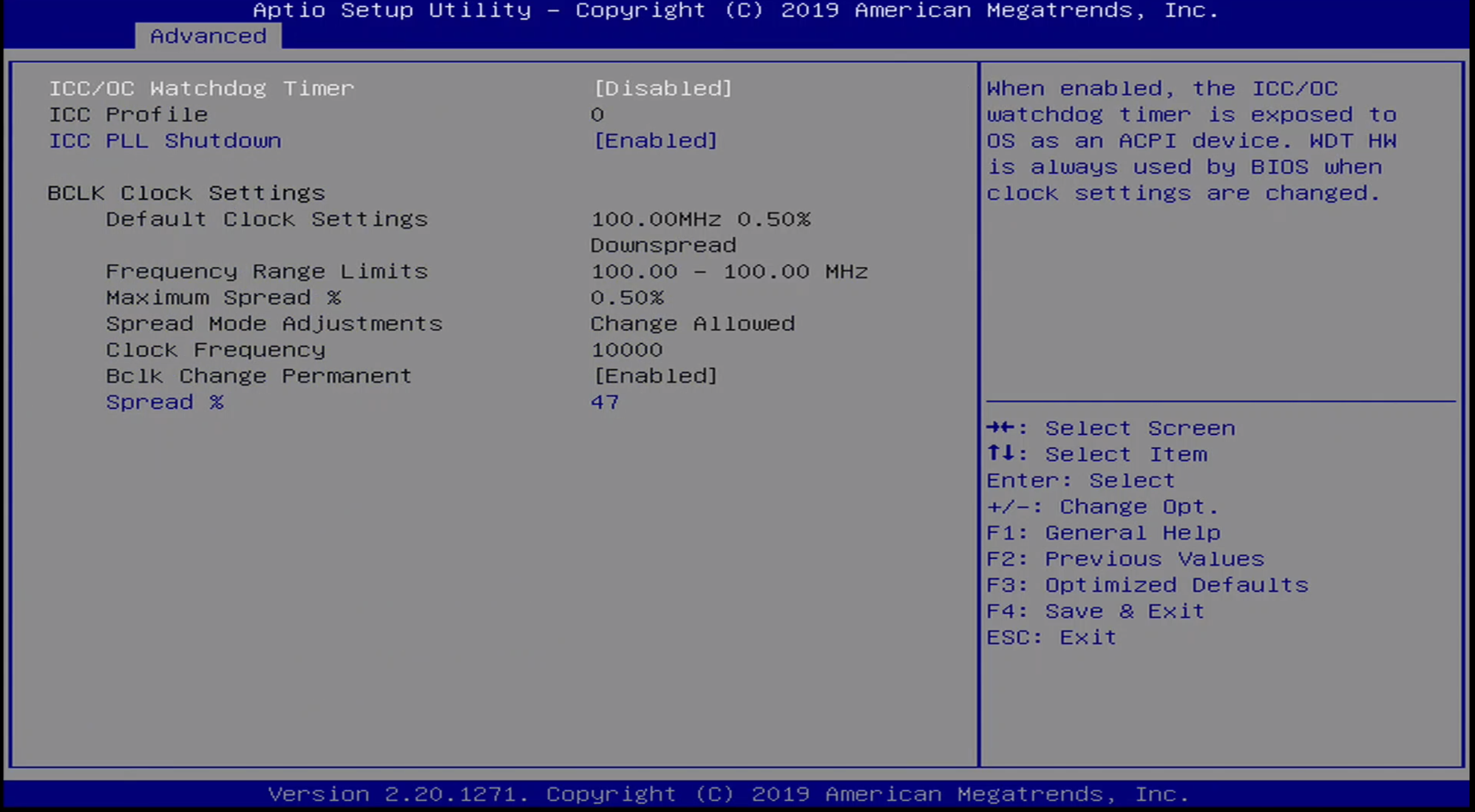
The Advanced / Intel ICC Menu includes the following configuration options:
- ICC/OC Watchdog Timer
- ICC Profile
- ICC PLL Shutdown
The following configuration information is also presented:
- BCLK Clock Settings
- Default Clock Settings
- Frequency Range Limits
- Maximum Spread %
- Spread Mode Adjustments
- Clock Frequency
- Bclk Change Permanent
- Spread %
Advanced / ThunderBolt(TM) Menu
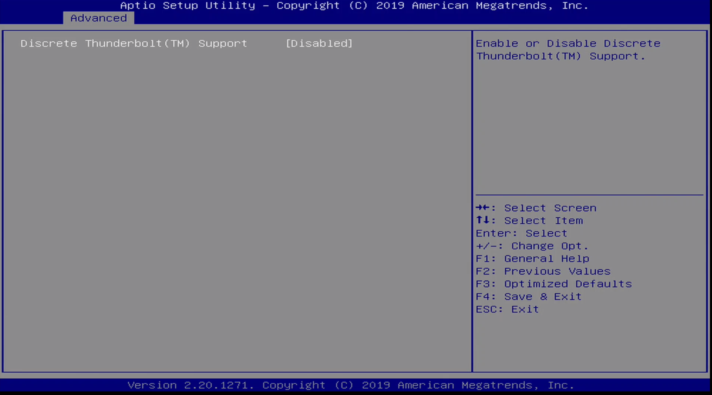
This menu allows the user to enabled/disable ThunderBolt(TM) support.
Advanced / Debug Settings Menu
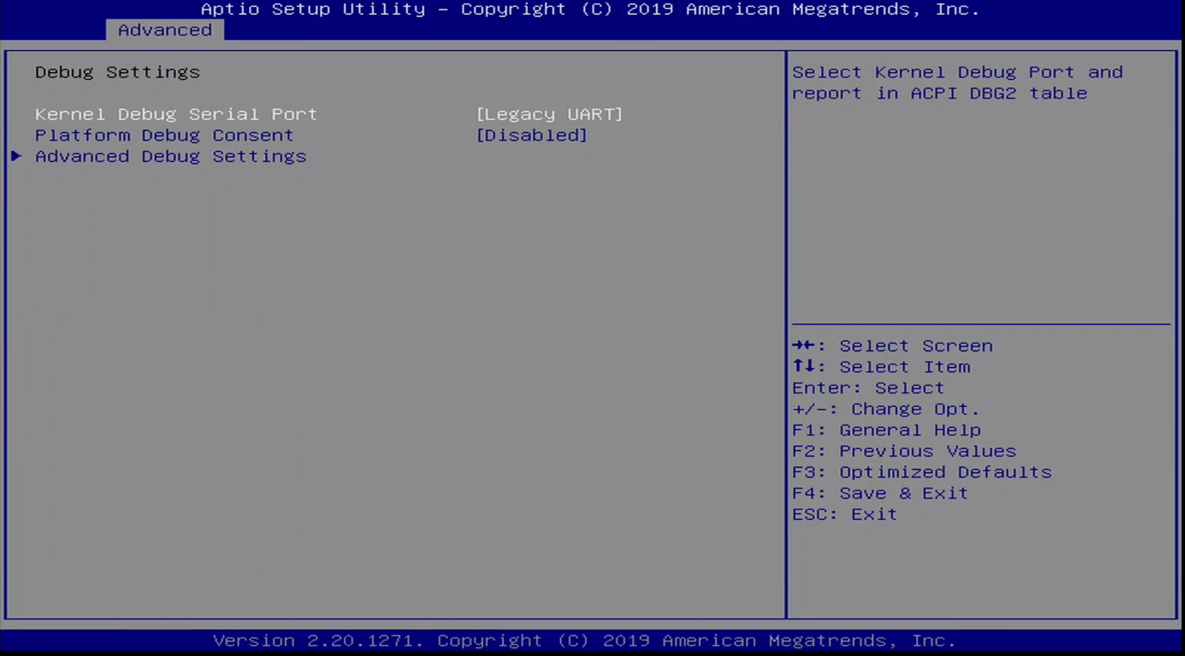
This menu allows a user to configure Intel DCI, amongst other platform configuration options. The sub options in this menu are:
- Kernel Debug Serial Port
- Platform Debug Consent
- Advanced Debug Settings
Advanced / Debug Settings Menu / Platform Debug Consent:
The options in this menu include:
- Disable
- Enabled (DCI OOB+[DbC])
- Enabled (DCI OOB)
- Enabled (USB3 DbC)
- Enabled (USB3 DbC)
- Enabled (XDP/MIPI60)
I have set this option to Enabled (DCI OOB) so we can use DCI to debug the platform. More information on this will be provided in the analysis section.
Advanced / Debug Settings Menu / Advanced Debug Menu
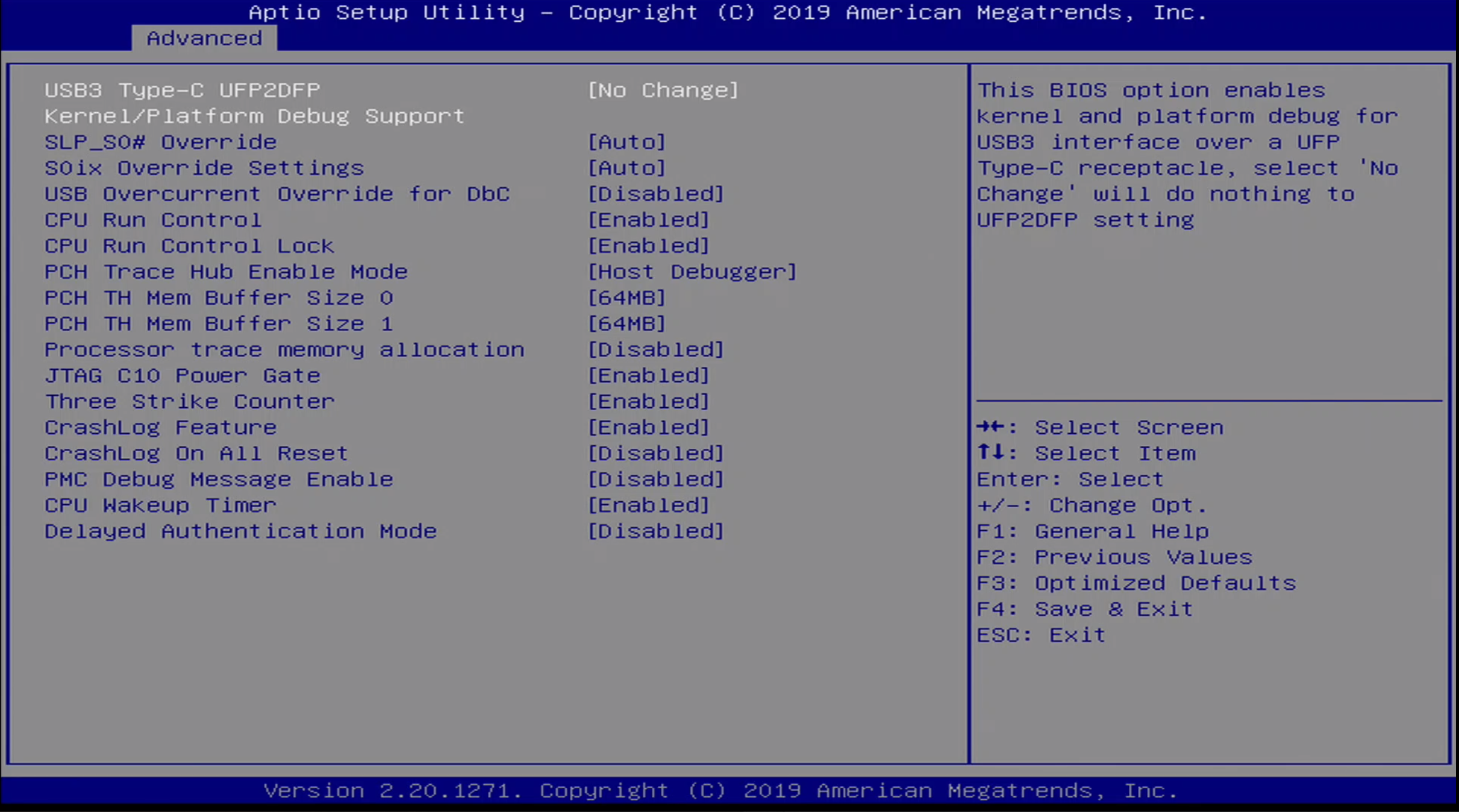
The Advanced / Debug Settings Menu / Advanced Debug Menu options are:
- USB 3 Type-C UFP2DFP Kernel/Platform Debug Support
- SLP_SO# Override
- SOix Override Settings
- USB Overcurrent Override for DbC
- CPU Run Control
- CPU Run Control Lock
- PCH Trace Hub Enable Mode
- PCH TH Mem Buffer Size 0
- PCH TH Mem Buffer Size 1
- Processor trace memory allocation
- JTAG C10 Power Gate
- Three Strikes Counter
- CrashLog Feature
- CrashLog On All Reset
- PMC Debug MEssage Enable
- CPU Wakeup Timer
- Delayed Authentication Mode
Advanced / Trusted Computing Menu
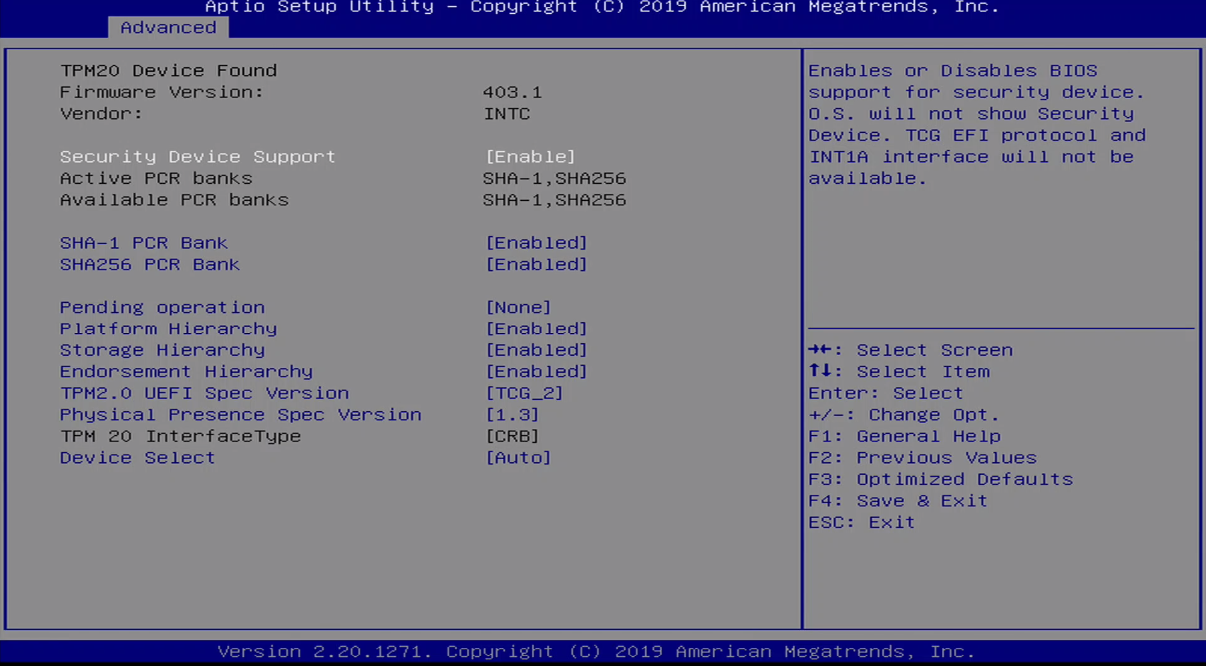
The Advanced / Trusted Computing Menu contains TPM information as well as the following options:
- Security Device Support
- SHA-1 PCR Bank
- SHA256 PCR Bank
- Pending Operation
- Platform Hierarchy
- Storage Hierarchy
- Endorsement Hierarchy
- TPM2.0 UEFI Spec Version
- Physical Presence Spec Version
- TPM 20 InterfaceType
- Device Select
Advanced / ACPI Menu
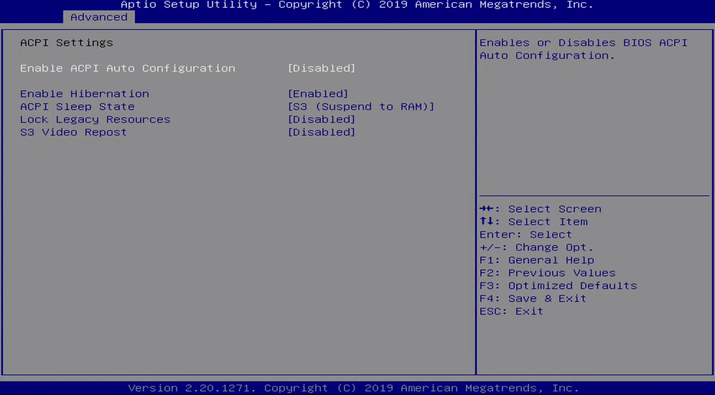
The Advanced / ACPI Menu contains the following configuration options:
- Enable ACPI Auto Configuration
- Enable Hibernation
- ACPI Sleep State
- Lock Legacy Resources
- S3 Video Repost
Advanced / S5 Menu
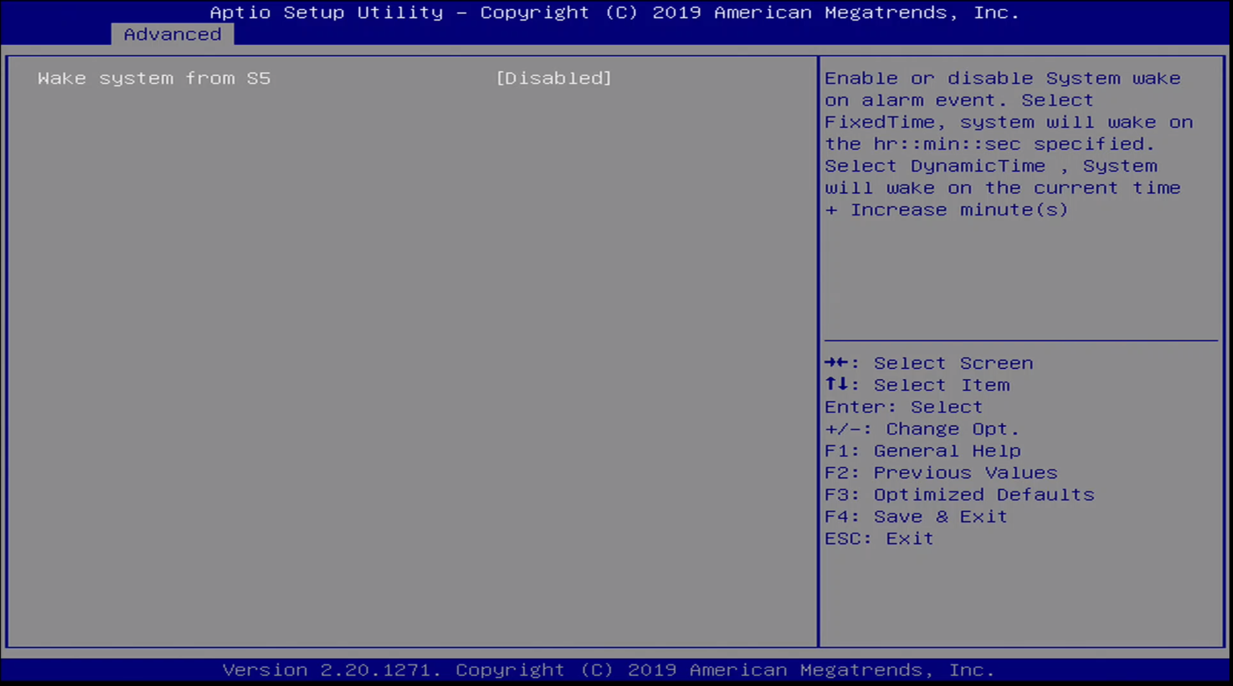
The Advanced / S5 menu allows the user to enable / disable Wake From S5.
Advanced / SMART Menu
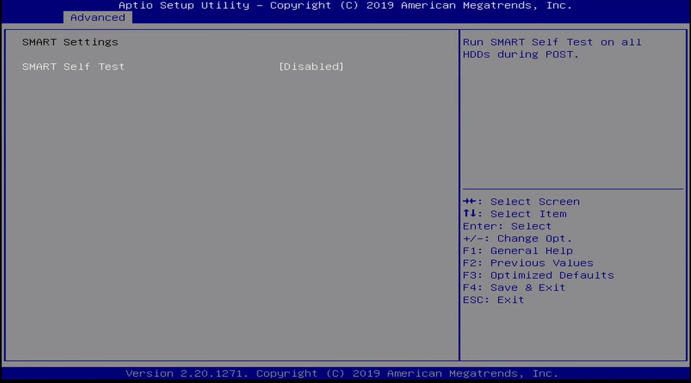
The Advanced / SMART Menu allows the user to enable / disable SMART.
Advanced / Serial Port Console Redirection Menu
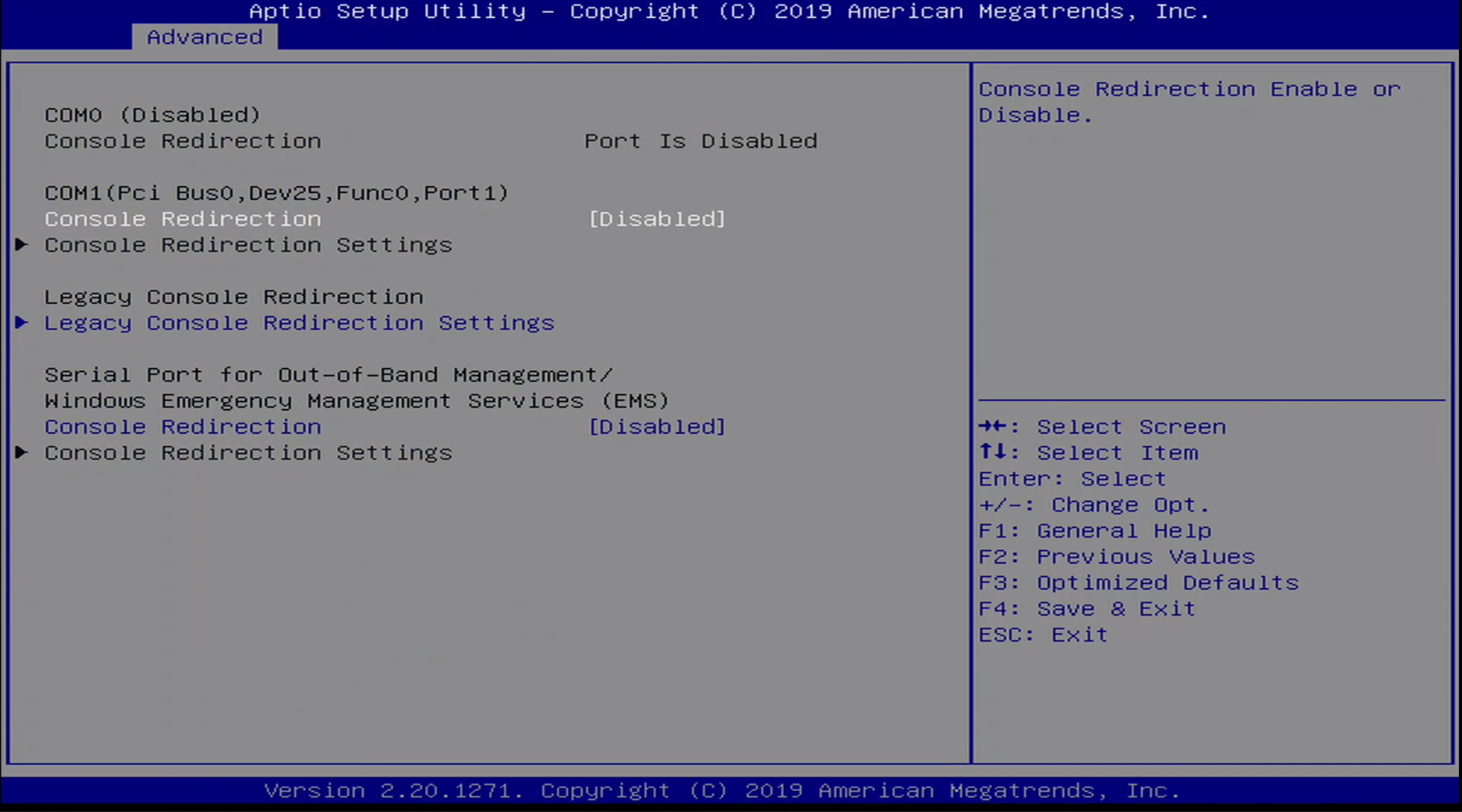
The Advanced / Serial Port Console Redirection Menu has the following options:
- Console Redirection
- Legacy Console Redirection Settings
- Windows Emergency Management Services Console Redirection
Advanced / Acoustic Management Configuration
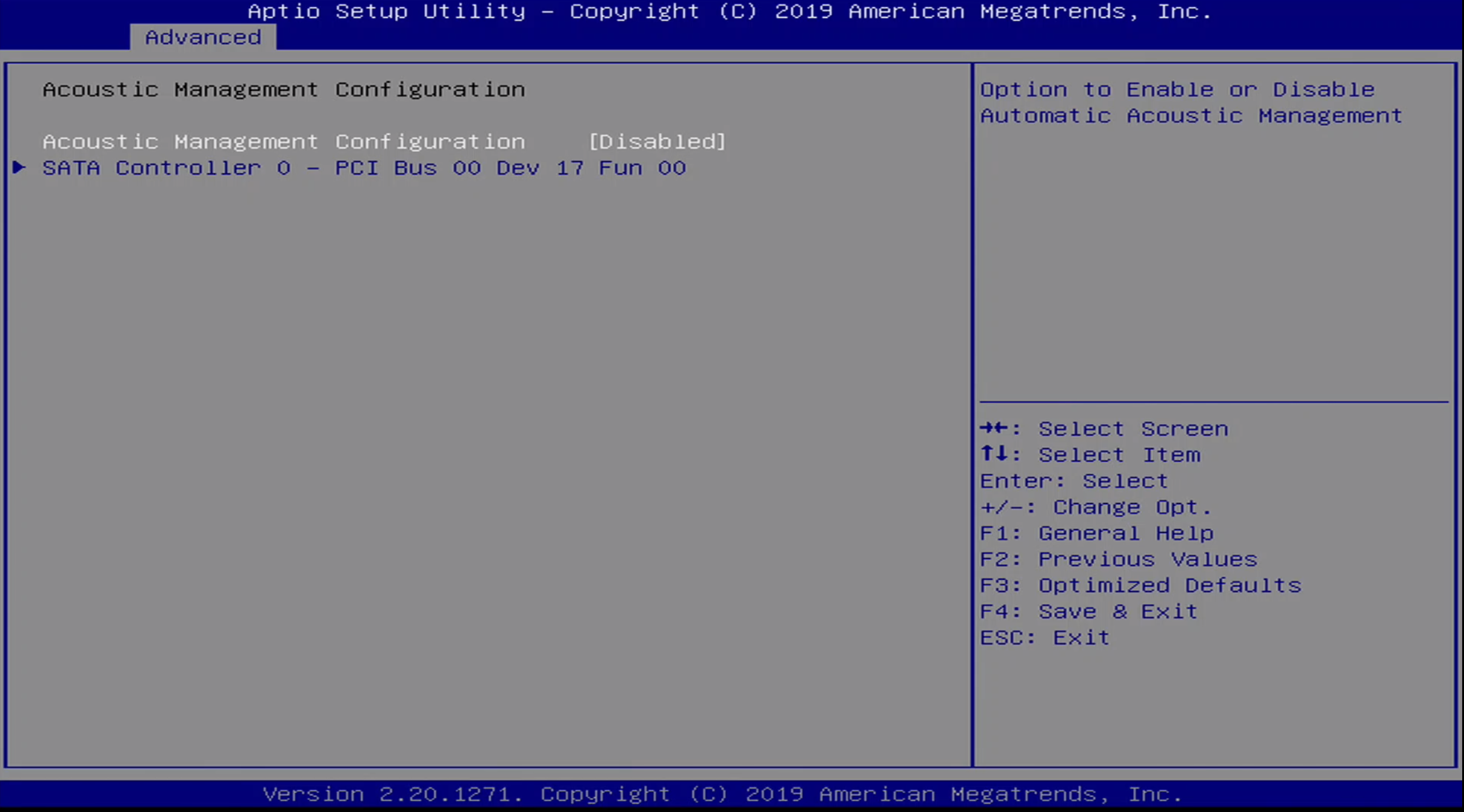
The Advanced / Acoustic Mangement Configuration Menu allows the user to enable / disable acoustic management of a given SATA device.
Advanced / Switchable Graphics Menu
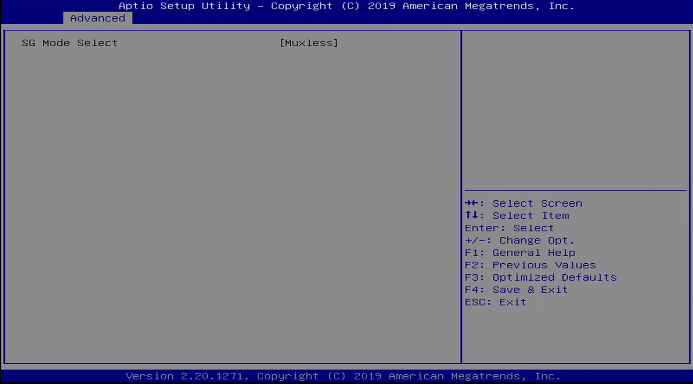
Advanced / AMT Graphics Menu

The Advanced / AMT Graphics Menu allows the user to set the output for AMT Graphics.
Advanced / PCI Settings Menu
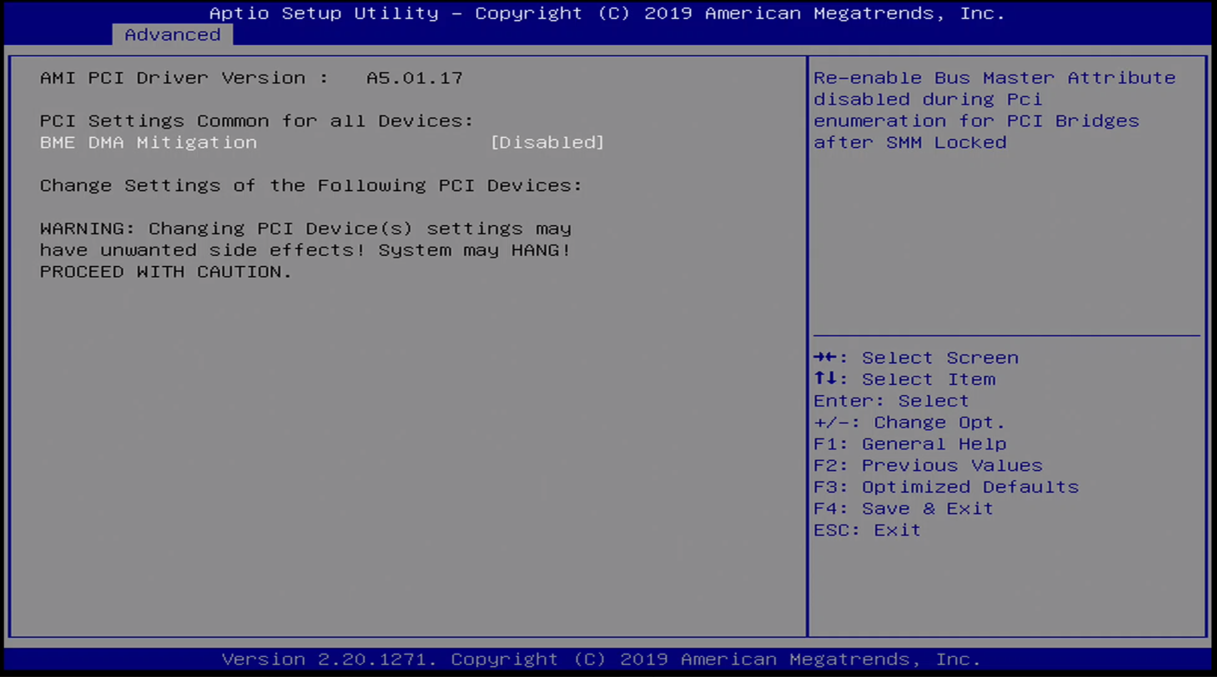
The Advanced / PCI Settings Menu allows BME DMA Mitigation to be enabled / disabled.
Advanced / USB Settings Menu
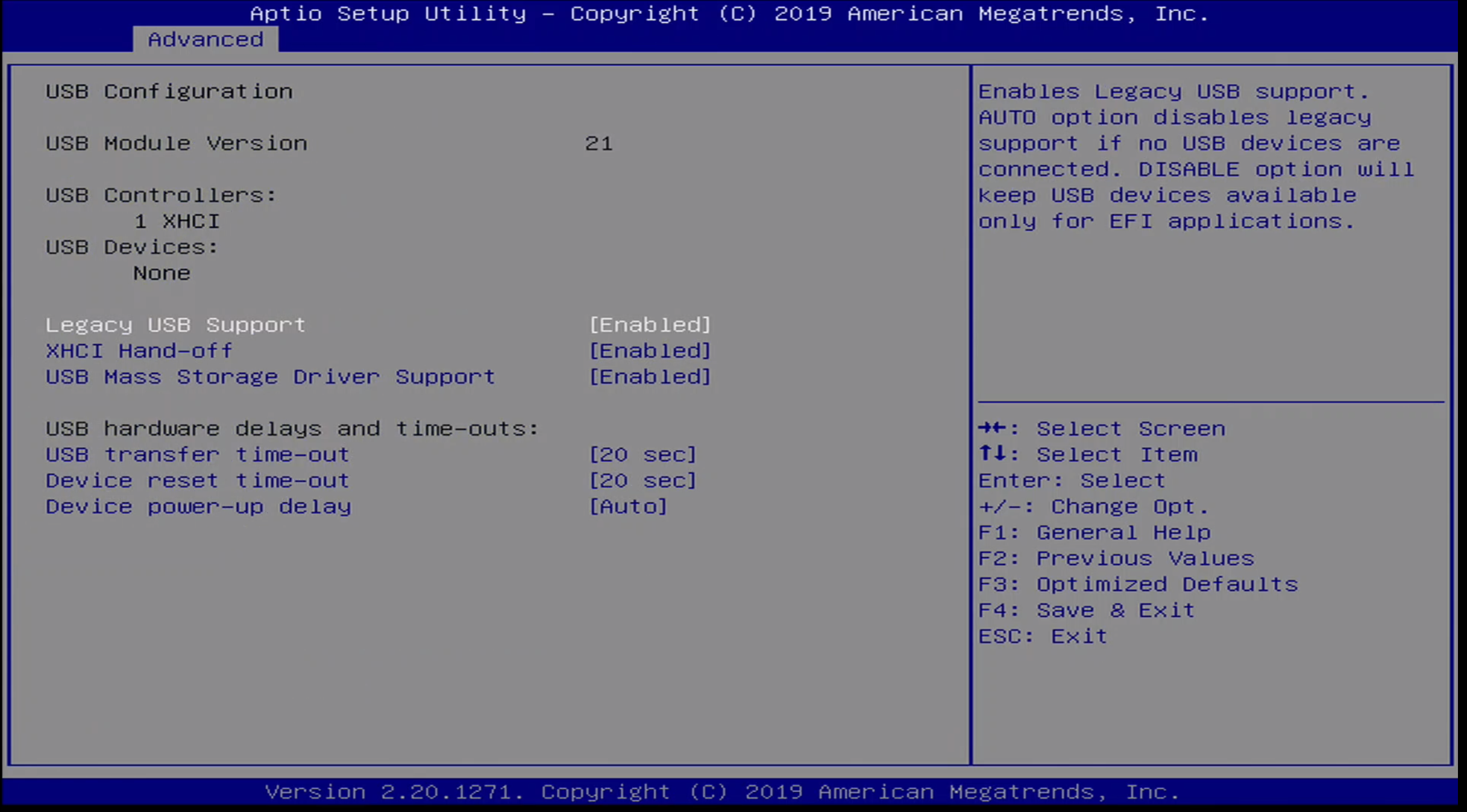
The Advanced / USB Settings menu contains the following configuration options:
- Legacy USB Support
- XHCI Hand-Off
- USB Mass Storage Driver Support
- USB transfer time-out
- Device reset time-out
- Device power-up delay
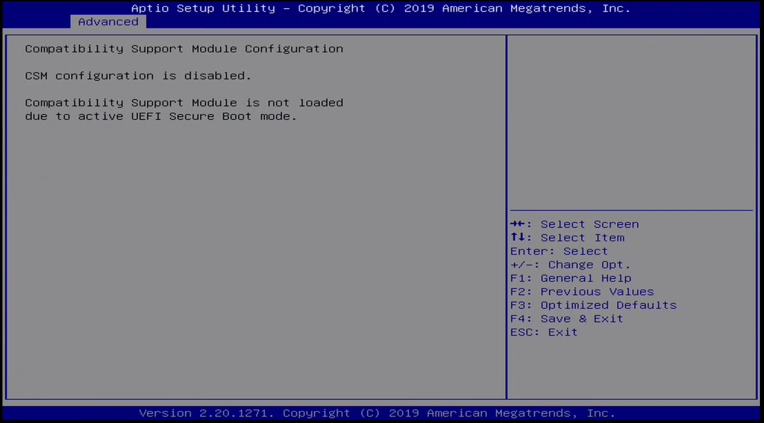
Advanced / CSM Menu
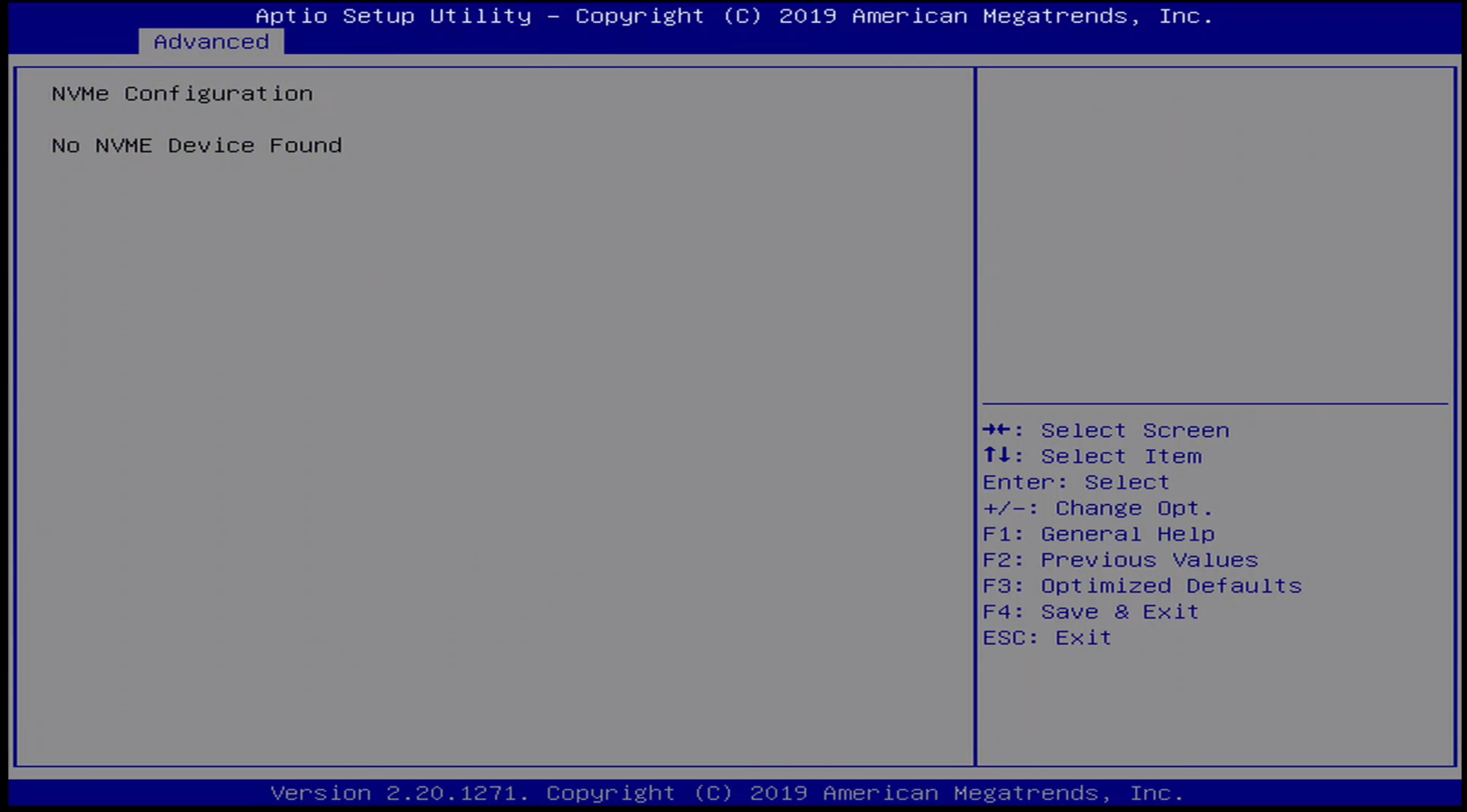
Advanced / NVMe Menu
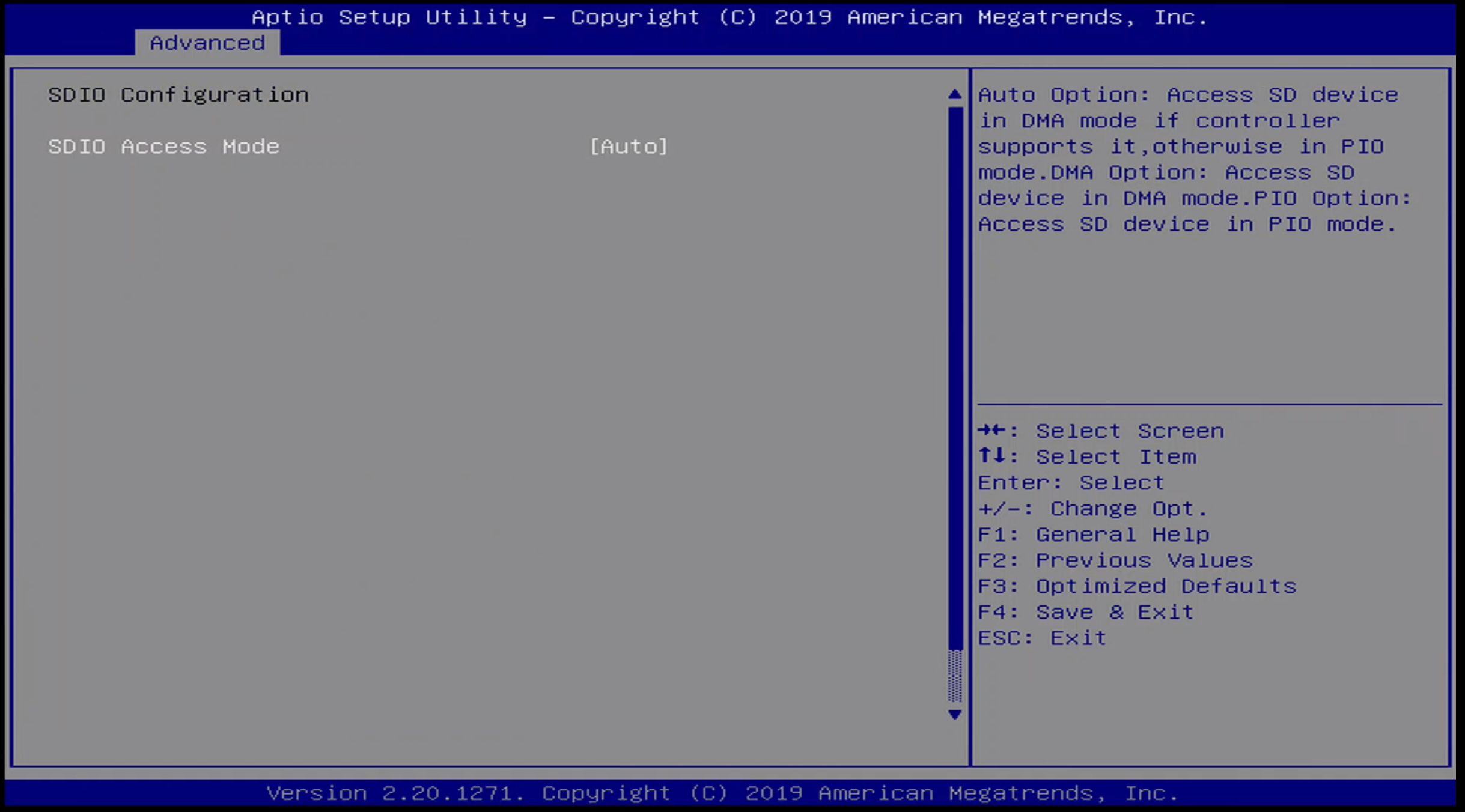
Advanced / SDIO Menu
Advanced / RAM Disk Menu
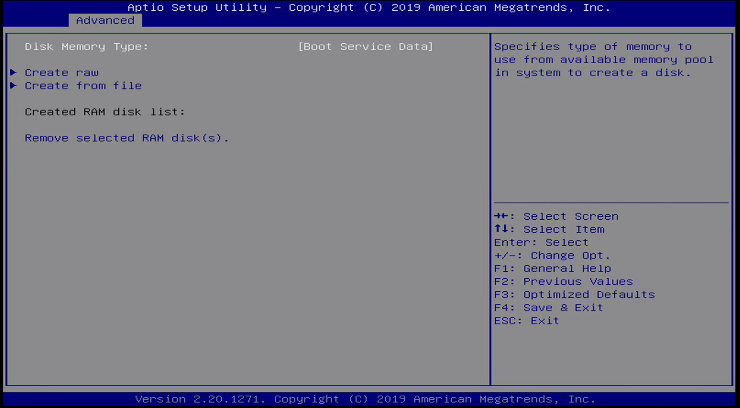
Advanced / Networking Stack Menu
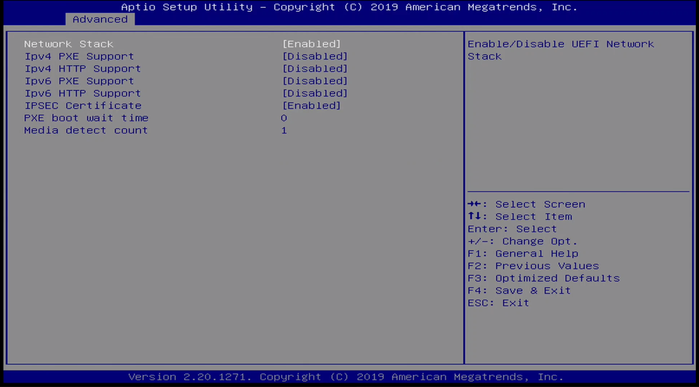
Advanced / Networking Options Menus
These next few networking stack-related options are only visible if networking has been enabled.
Advanced / VLAN Menu
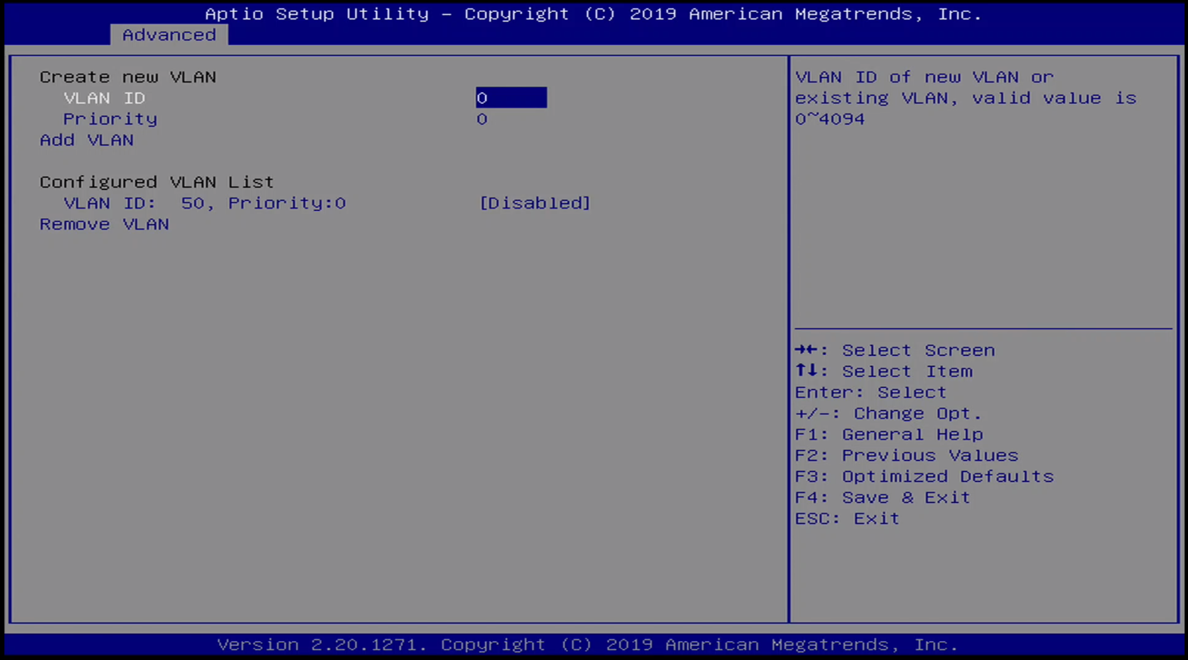
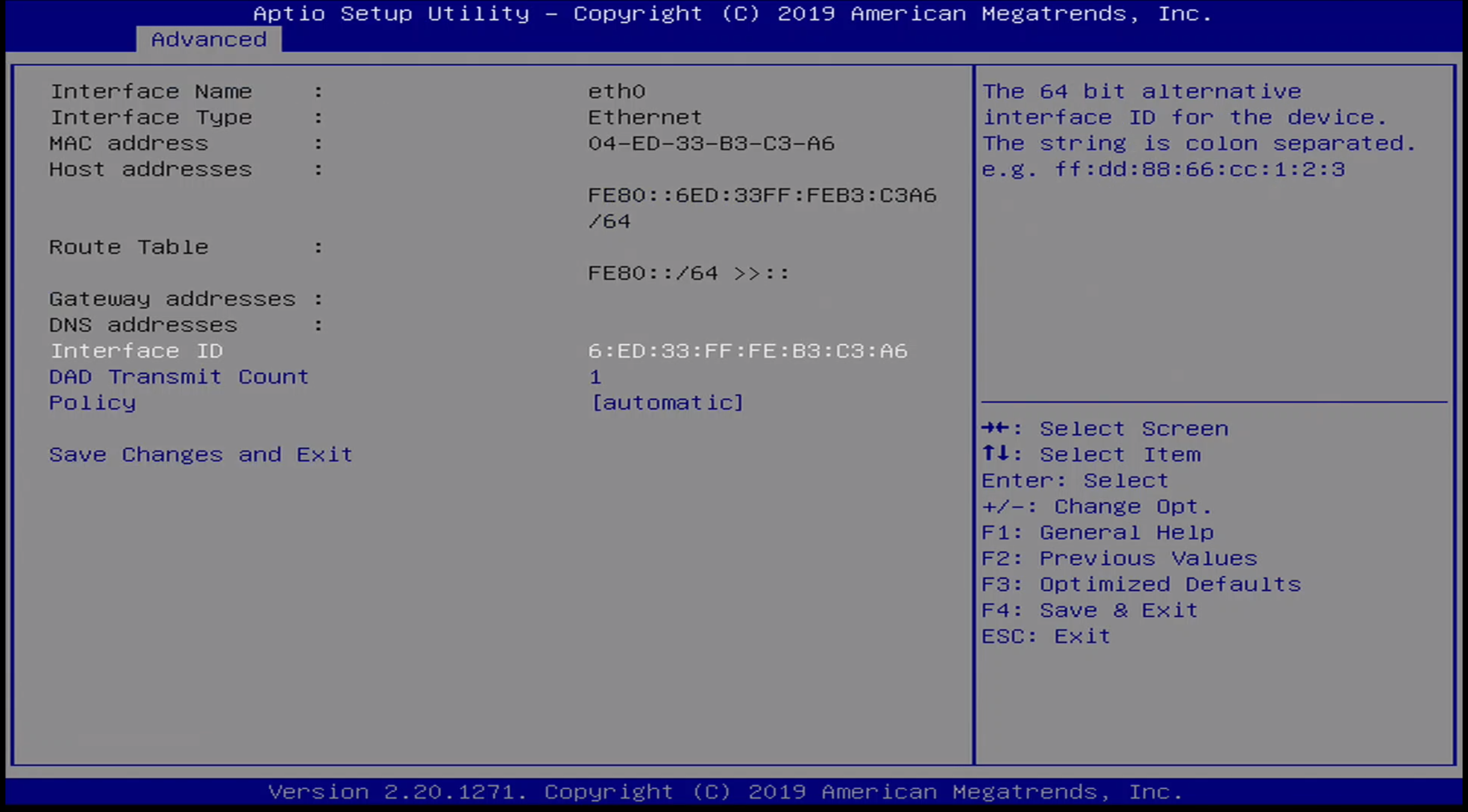
Advanced / Ethernet Interface Menu
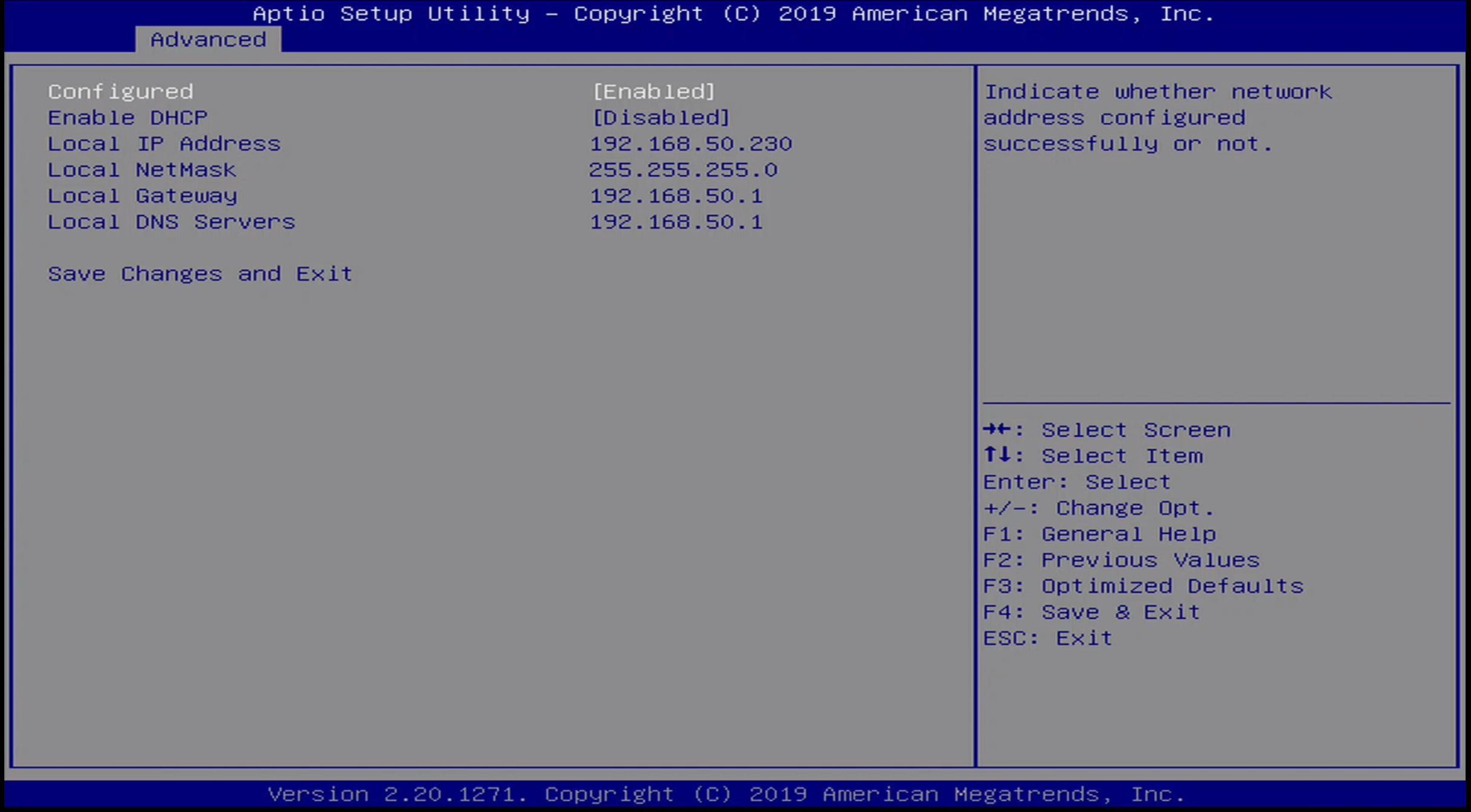
Advanced / UEFI HTTP Boot Menu

Advanced / Ethernet Menu
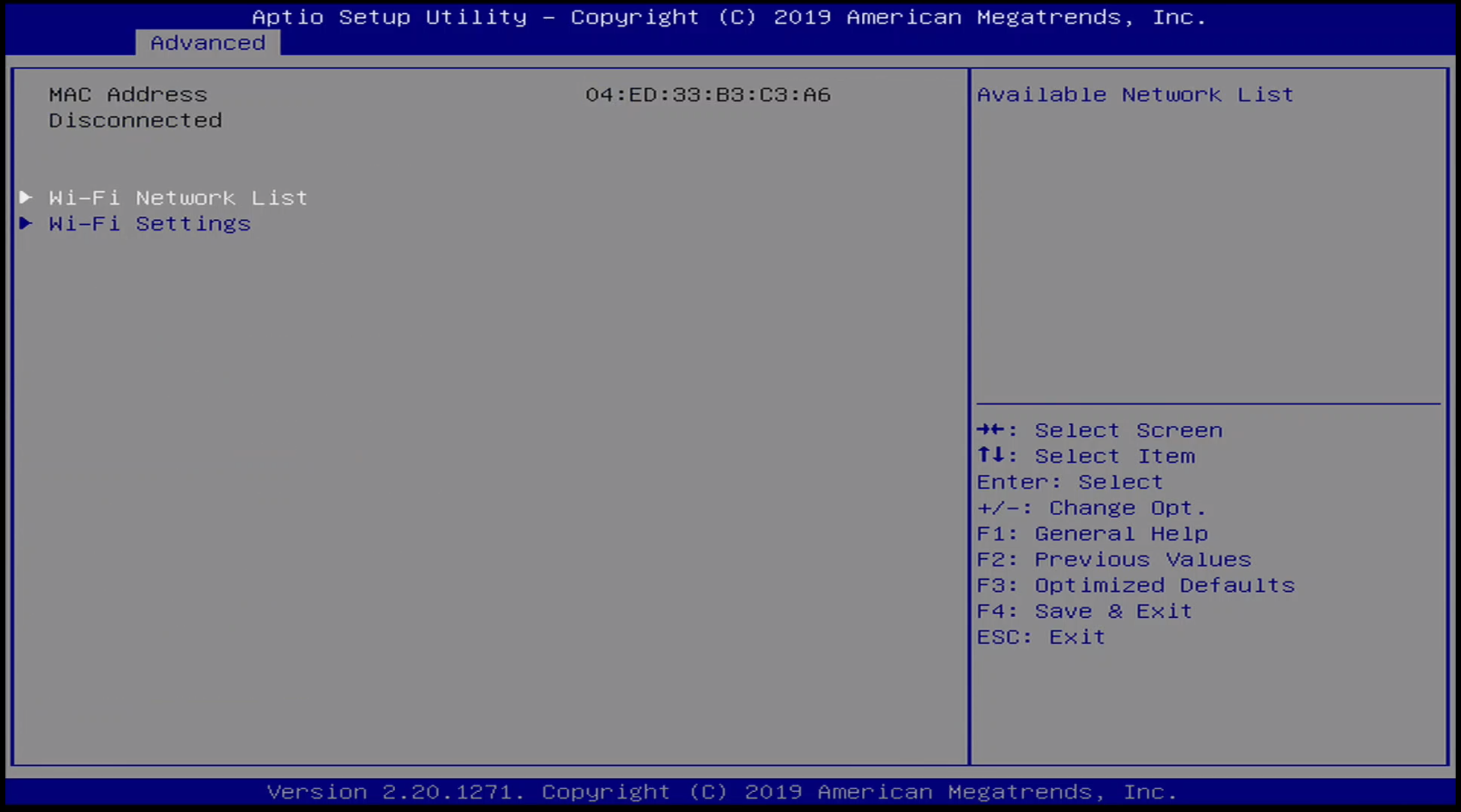
Advanced / WiFi Menu
Chipset Menu
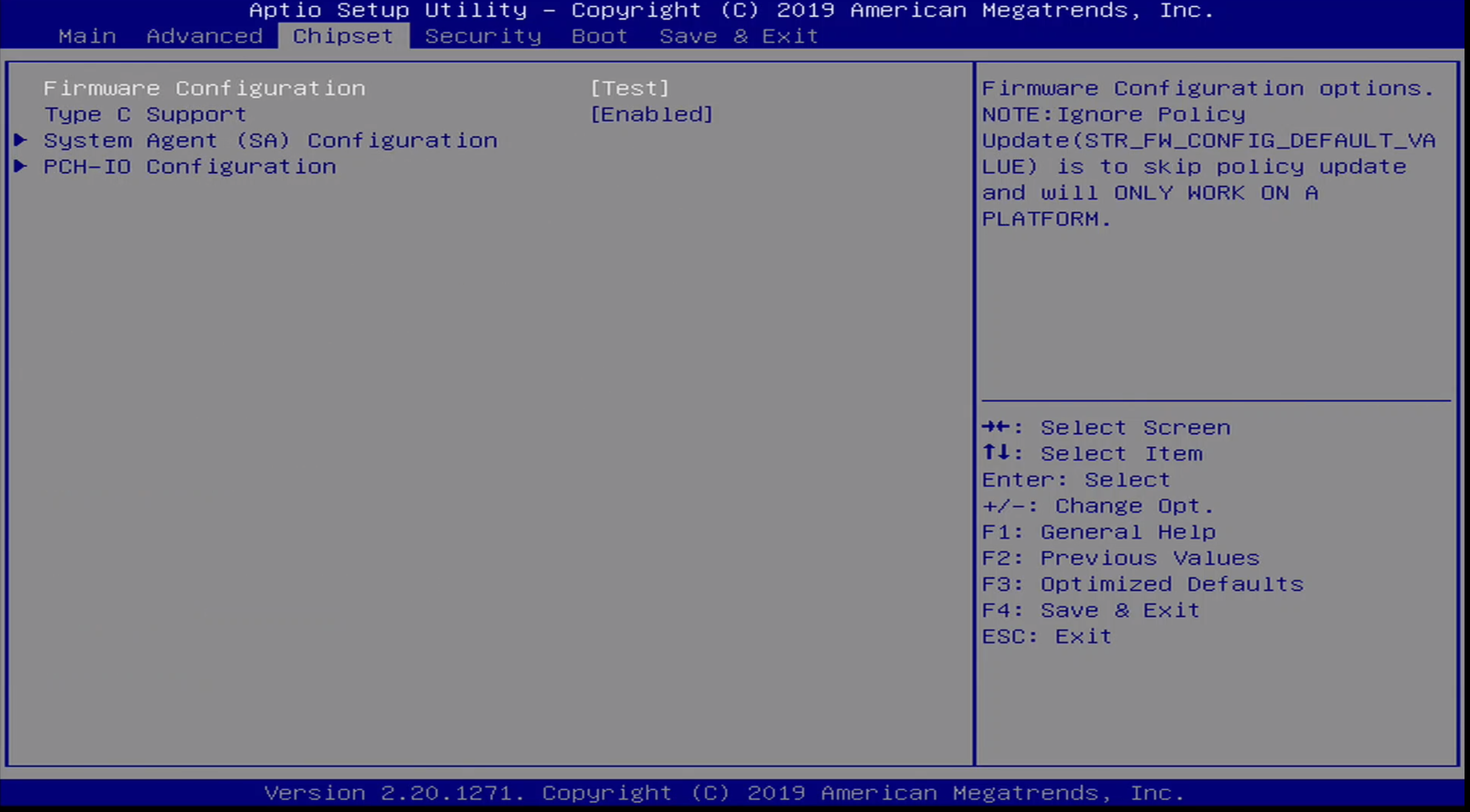
The chipset menu contains a few additional platform configuration options. The sub-menu’s available here are:
- Firmware Configuration
- Type C Support
- System Agent Configuration
- PCH-IO Configuration
Note that by default, the Firmware Configuration is set to [Test] .
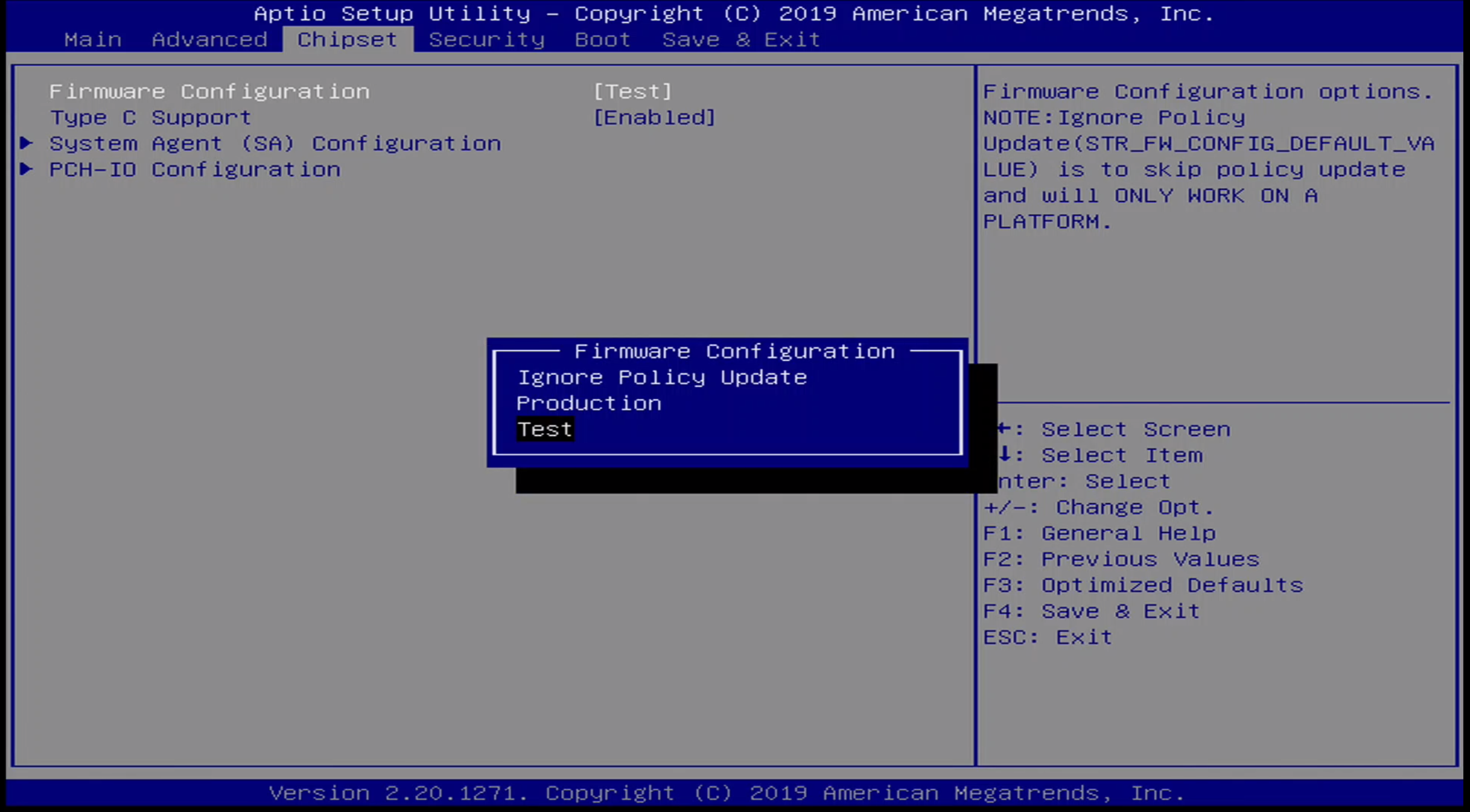
Additional options for Firmware Configuration include:
- Ignore Policy Update
- Production
- Test
Chipset / Graphics Configuration
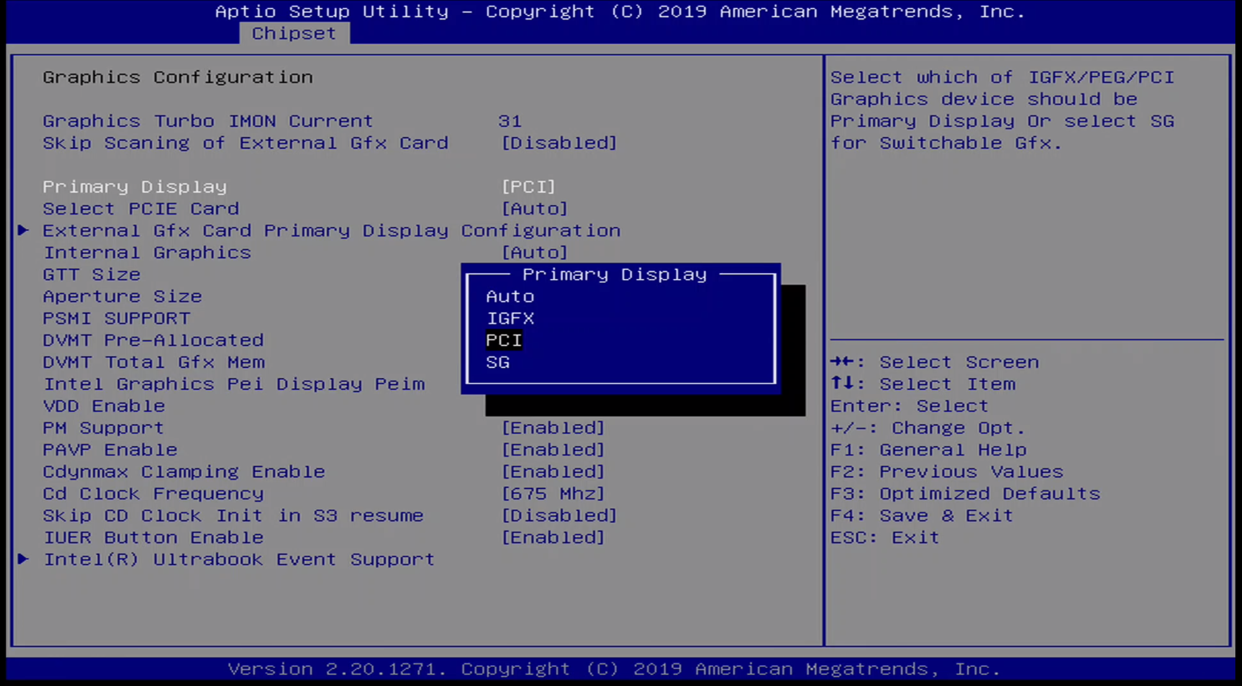
The following options are availabe for primary display:
- Auto
- IGFX
- PCI
- SG
I set this option to PCI to work with my HDMI capture card. By default it is set to auto .
Security Menu
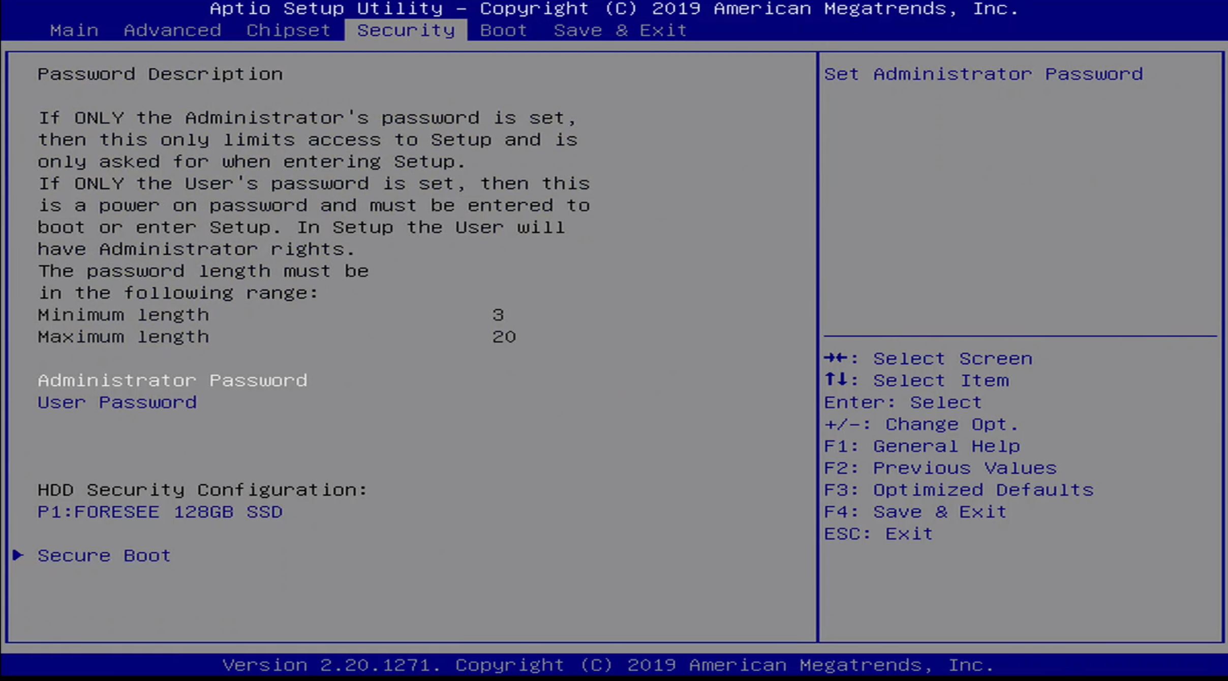
The Security menu allows the user to set an Administrator Password or a User Password . The Administrator Password allows access to BIOS Setup, while the User Password allows POST and access to BIOS Setup.
Additionally, Secure Boot can be configured in this menu.
Security / Secure Boot Menu
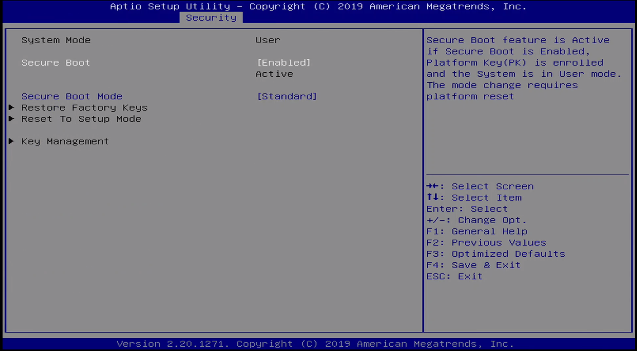
There are two options for Secure Boot Mode:
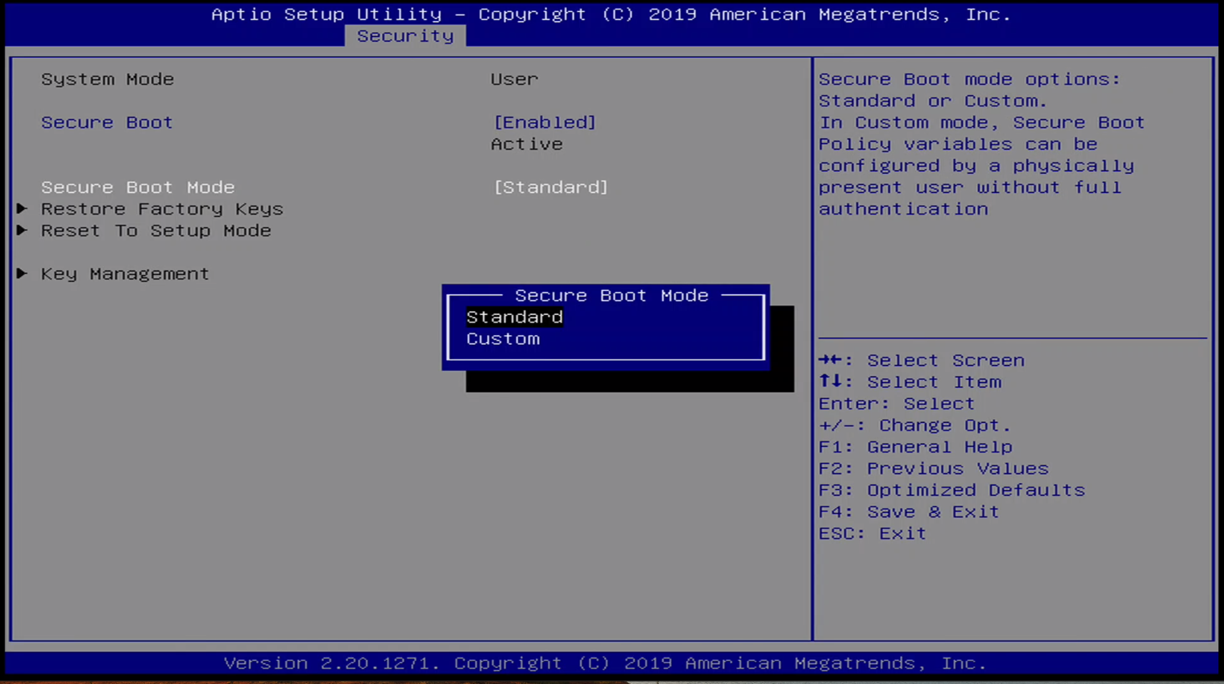
- Standard
- Custom
Note the Secure Boot is enabeld by default.
Boot Menu
The Boot Menu presents the user with options as to boot device order.
Save & Exit Menu
The Save & Exit Menu presents the user with options to save BIOS configuration settings as well as to override the boot settings
Update 10/13/2021
@RockerFernando reached out to me with some additional details. Apparently there are Gateway-branded laptops that have the same BIOS as the ONN-branded laptop. Like me, he had bricked his laptop by setting the same BIOS option. I was pretty sure that by resetting the NVRAM we could restore our laptops to a usable state, and @RockerFernando went and figured out how to do this. If you open the chassis and disconnect the battery, or simply wait a few months until the battery is totally dead, and then hold down the power button for about a minute, you should be able to reset NVRAM thus clearing the faulty configuration value. Thanks @RockerFernando for the tip!
6. BIOS Setup Utility
Power on the computer and press Delete during the beginning of the boot sequence to enter the BIOS Setup Utility. If the entry point has passed, restart the system and try again.
6.2. Control Keys
Key Function Up Move up one row Down Move down one row Left Move to the left in the navigation bar Right Move to the right in the navigation bar Enter Access the highlighted item / Select the item Esc Jumps to the Exit screen or returns to the previous screen + [1] Increase the numeric value — [1] Decrease the numeric value F1 General help [2] F2 Previous value F3 Load optimized defaults F4 Save all the changes and exit [1] (1, 2) Must be pressed using the 10-key pad. [2] The General help contents are only for the Status Page and Option Page setup menus. 6.3. Getting Help
The BIOS Setup Utility provides a General Help screen. This screen can be accessed at any time by pressing F1. The help screen displays the keys for using and navigating the BIOS Setup Utility. Press Esc to exit the help screen.
6.4. System Overview
The System Overview screen is the default screen that is shown when the BIOS Setup Utility is launched. This screen can be accessed by traversing the navigation bar to the “Main” label.
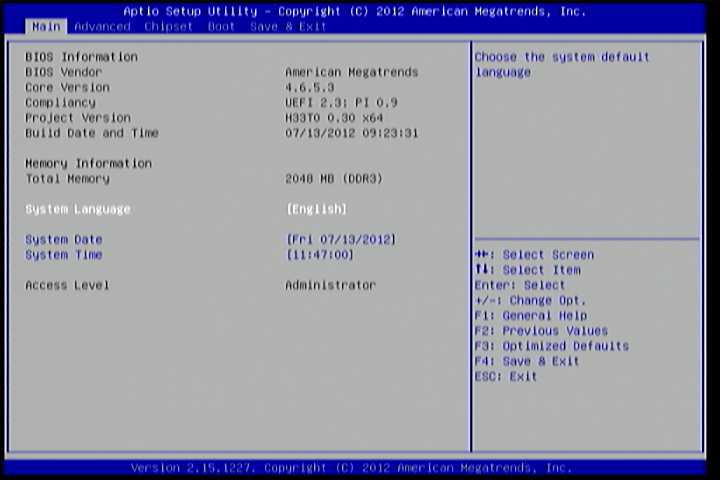
Figure 1: Illustration of the Main menu screen
6.4.1. BIOS Information
The content in this section of the screen shows the information about the vendor, the Core version, UEFI specification version, the project version and date & time of the project build.
6.4.2. Memory Information
This section shows the amount of memory that is installed on the hardware platform.
6.4.3. System Language
This option allows the user to configure the language that the user wants to use.
6.4.4. System Date
This section shows the current system date. Press Tab to traverse right and Shift+Tab to traverse left through the month, day, and year segments. The + and — keys on the number pad can be used to change the values. The weekday name is automatically updated when the date is altered. The date format is [Weekday, Month, Day, Year].
6.4.5. System Time
This section shows the current system time. Press Tab to traverse right and Shift+Tab to traverse left through the hour, minute, and second segments. The + and — keys on the number pad can be used to change the values. The time format is [Hour : Minute : Second].
6.5. Advanced Settings
The Advanced Settings screen shows a list of categories that can provide access to a sub-screen. Sub-screen links can be identified by the preceding right-facing arrowhead.
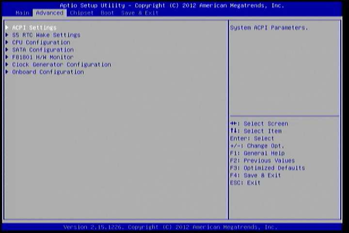
Figure 2: Illustration of the Advanced Settings screen
The Advanced Settings screen contains the following links:
- ACPI Settings
- S5 RTC Wake Settings
- CPU Configuration
- SATA Configuration
- F81801 H/W Monitor
- Clock Generator Configuration
- Onboard Configuration
6.5.1. ACPI Settings
ACPI grants the operating system direct control over system power management. The ACPI Configuration screen can be used to set a number of power management related functions.
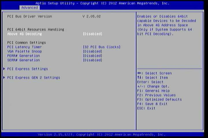
Figure 3: Illustration of the ACPI Settings screen
6.5.1.1. Enable Hibernation
Enable/disable system ability to Hibernate.
6.5.1.2. ACPI Sleep State
Select the highest ACPI sleep state the system will enter when the SUSPEND button is selected. Available options are:
- Suspend Disabled
- S1(CPU Stop Clock)
- S3 (Suspend to RAM)
- Both S1 and S3 available for OS to choose.
6.5.2. S5 RTC Wake Settings
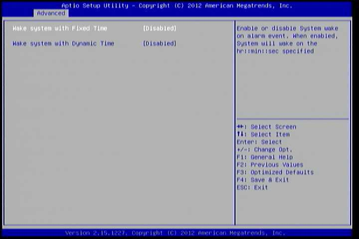
Figure 4: Illustration of the S5 RTC Wake Settings screen
6.5.2.1. Wake system with Fixed Time
Enable or disable system wake on alarm event. When enabled, system will wake on the hr:min:sec specified.
6.5.2.2. Wake system with Dynamic Time
Enable or disable Wake system with Dynamic Time.
6.5.3. CPU Configuration
The CPU Configuration screen shows detailed information about the built-in processor. In addition to the processor information, the thermal controls can be set.
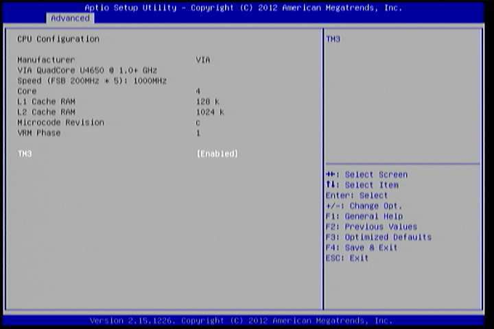
Figure 5: Illustration of CPU Configuration screen
6.5.3.1. TM3
The TM3 Function has two settings: Disabled and Enabled. When the setting is changed to “Disabled”, the CPU’s built-in thermal sensor will not function. When the setting is changed to “Enabled”, the thermal sensor will automatically adjust the CPU ratio and V CORE to prevent the CPU from overheating.
6.5.4. SATA Configuration
The SATA Configuration screen allows the user to view and configure the settings of the SATA configuration settings.
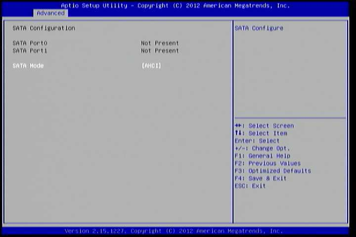
Figure 6: Illustration of SATA Configuration screen
6.5.4.1. SATA Mode
This option allows the user to manually configure SATA controller for a particular mode.
- IDE Mode: Set this value to change the SATA to IDE mode.
- AHCI Mode: Set this value to change the SATA to AHCI mode.
6.5.5. PC Health Status
The PC Health Status screen has no editable fields. The system temperature is taken from an optional sensor that is connected to the J5 pin header.
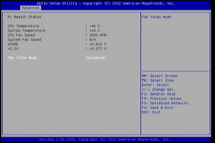
Figure 7: Illustration of PC Health Status screen
6.5.5.1. Fan Turbo Mode
This option allows the user to Enable or Disable Fan Turbo Mode.
6.5.6. Clock Generator Configuration
The Clock Generator Configuration screen enables access to the Spread Spectrum Setting feature.
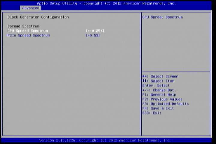
Figure 8: Illustration of Clock Generator Configuration screen
6.5.6.1. CPU Spread Spectrum
The Spread Spectrum Setting feature enables the BIOS to modulate the clock frequencies originating from the mainboard. The settings are in percentages of modulation. Higher percentages result in greater modulation of clock frequencies. This feature has 3 options: Disable, +-0.25% and -0.5%.
6.5.6.2. PCIe Spread Spectrum
Select PCIe Spread Spectrum. This feature has 2 options: Disable and -0.5%.
6.5.7. OnBoard Device Configuration
The OnBoard Device Configuration screen has the following features.
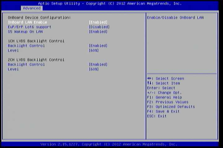
Figure 9: Illustration of OnBoard Device Configuration screen
6.5.7.1. OnBoard LAN Enable
The OnBoard LAN Enable feature determines whether the onboard LAN controller will be used or not.
6.5.7.2. EuP/ErP Lot6 support
The EuP/ErP Lot6 Support feature enables the BIOS to reduce the power draw to less than 1W when the system is in standby mode. This feature has two options: enabled and disabled.
6.5.7.3. S5 Wakeup On LAN
The S5 Wakeup On LAN feature enables the BIOS to allow remote wake-up from the S5 power off state through the PCI bus.
6.5.7.4. 1CH LVDS Backlight Control
Backlight Control
The Backlight Control feature control by VX11H enables the user to control the brightness of the 1CH LVDS backlight. This feature has six options.
Level 0%, 20%, 40%, 60%, 80% and 100%.
6.5.7.5. 2CH LVDS Backlight Control
Backlight Control
The Backlight Control feature control by VX11H enables the user to control the brightness of the 2CH LVDS backlight. This feature has six options.
Level
0%, 20%, 40%, 60%, 80% and 100%.
6.6. Chipset Settings
The Chipset Settings screen shows a list of categories that can provide access to a sub-screen. Sub-screen links can be identified by the preceding right- facing arrowhead.
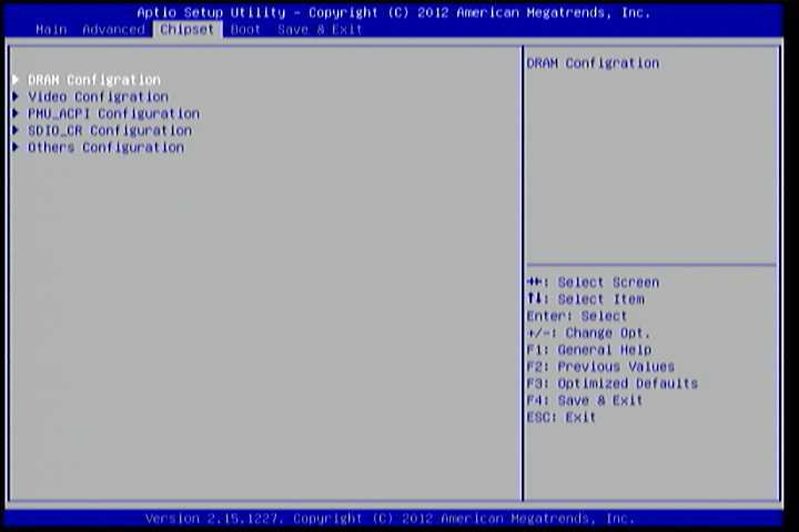
Figure 10: Illustration of Chipset Settings screen
The Chipset Settings screen contains the following links:
- DRAM Configuration
- Video Configuration
- PMU-ACPI Configuration
- SDIO_CR Configuration
- Others Configuration
6.6.1. DRAM Configuration
The DRAM Configuration screen has two features for controlling the system DRAM. All other DRAM features are automated and cannot be accessed.
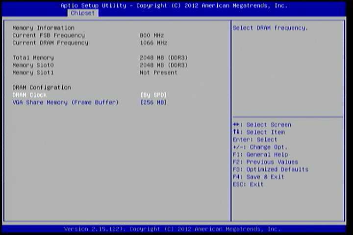
Figure 11: Illustration of DRAM Configuration screen
6.6.1.1. DRAM Clock
The DRAM Clock option enables the user to determine how the BIOS handles the memory clock frequency. The memory clock can either be dynamic or static. This feature has eleven options.
By SPD
By SPD option enables the BIOS to select a compatible clock frequency for the installed memory.
400 MHz
The 400 MHz option forces the BIOS to be fixed at 800 MHz for DDR3 memory modules.
533 MHz
The 533 MHz option forces the BIOS to be fixed at 1066 MHz for DDR3 memory modules.
566 MHz
The 566 MHz option forces the BIOS to be fixed at 1132 MHz for DDR3 memory modules.
600 MHz
The 600 MHz option forces the BIOS to be fixed at 1200 MHz for DDR3 memory modules.
633 MHz
The 633 MHz option forces the BIOS to be fixed at 1266 MHz for DDR3 memory modules.
667 MHz
The 667 MHz option forces the BIOS to be fixed at 1334 MHz for DDR3 memory modules.
6.6.1.2. VGA Share Memory (Frame Buffer)
The VGA Share Memory feature enables the user to choose the amount of the system memory to reserve for use by the integrated graphics controller. The selections of memory amount that can be reserved are 256MB and 512MB.
6.6.2. Video Configuration
The Video Configuration screen has features for controlling the integrated graphics controller in the VX11H chipset.
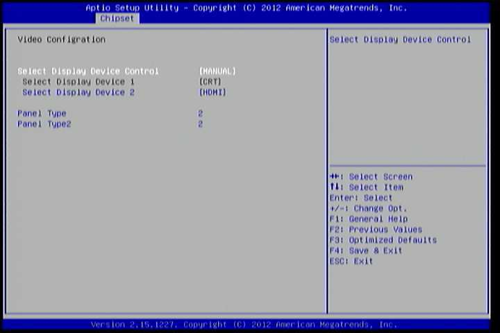
Figure 12: Illustration of Video Configuration screen
6.6.2.1. Select Display Device Control
Available selections are: Auto and Manual.
6.6.2.2. Select Display Device 1 and 2
The Select Display Device feature enables the user to choose a specific display interface. This feature has four options: CRT, LCD, LCD2 and HDMI. If both Select Display Device 1 and Select Display Device 2 are set to the same interface, then any display device connected to the other interface will not function. For example, if both Select Display 1 and 2 are set to CRT, then no data will be sent to the HDMI, LCD and LCD2 port.
6.6.2.3. Panel Type
The Panel Type feature enables the user to specify the resolution of the display being used with the system. The panel types are predefined in the VGA VBIOS.
Panel Type Resolution Panel Type Resolution 00 640 x 480 08 800 x 480 01 800 x 600 09 1024 x 600 02 1024 x 768 10 1366 x 768 03 1280 x 768 11 1600 x 1200 04 1280 x 1024 12 1680 x 1050 05 1400 x 1050 13 1920 x 1200 06 1440 x 900 14 1920 x 1080 07 1280 x 800 15 1024 x 576 6.6.2.4. Panel Type2
The Panel Type feature enables the user to specify the resolution of display 2 being used with the system. The panel types are predefined in the VGA VBIOS.
Panel Type Resolution Panel Type Resolution 00 640 x 480 08 800 x 480 01 800 x 600 09 1024 x 600 02 1024 x 768 10 1366 x 768 03 1280 x 768 11 1600 x 1200 04 1280 x 1024 12 1680 x 1050 05 1400 x 1050 13 1920 x 1200 06 1440 x 900 14 1920 x 1080 07 1280 x 800 15 1024 x 576 6.6.3. PMU_ACPI Configuration
The PMU_ACPI Configuration screen can be used to set a number of power management related functions.
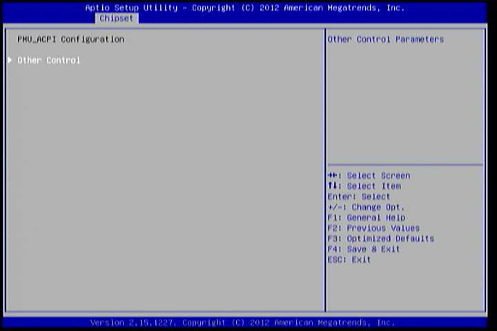
Figure 13: Illustration of PMU_ACPI Configuration screen
6.6.3.1. Other Control
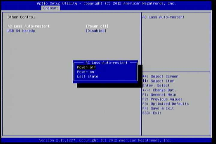
Figure 14: Illustration of Other Control screen
AC Loss Auto-restart
AC Loss Auto-restart defines how the system will respond after AC power has been interrupted while the system is on. There are three options.
The Power Off option keeps the system in an off state until the power button is pressed again.
The Power On option restarts the system when the power has returned.
The Last State option restores the system to its previous state when the power was interrupted.
USB S4 WakeUp
The USB S4 WakeUp enables the system to resume through the USB device port from S4 state. There are two options: “Enabled” or “Disabled”.
6.6.4. SDIO_CR Configuration
The SDIO_CR Configuration screen can be used to set SDIO_CR configuration parameters.
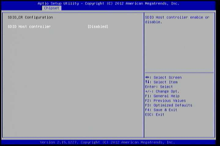
Figure 15: Illustration of SDIO_CR Configuration screen
6.6.4.1. SDIO Host Controller
Available selections are: Enabled and Disabled.
6.6.4.2. SDIO Specification Ver3.0 Support
Available selections are: Enabled and Disabled.
6.6.4.3. Voltage Support 1.8v
Available selections are: Enabled and Disabled.
6.6.4.4. High Speed Support
Available selections are: Enabled and Disabled.
6.6.4.5. Driver Type Select
Available selections are: Type A, Type B, Type C and Type D.
6.6.4.6. SDR50 Support
Available selections are: Enabled and Disabled.
6.6.4.7. SDR104 Support
Available selections are: Enabled and Disabled.
6.6.4.8. DDR50 Support
Available selections are: Enabled and Disabled.
6.6.4.9. SDR50 Tuning Enable
Available selections are: Enabled and Disabled.
6.6.4.10. Timer Count for Re-Tuning
Available selections are:
- 1 second
- 2 seconds
- 4 seconds
- 8 seconds
- 16 seconds
- 32 seconds
- 64 seconds
- 120 seconds
- 256 seconds
- 512 seconds
- 1024 seconds
- get information from other source
6.6.4.11. Card Reader Host Controller 0
Available selections are: Enabled and Disabled.
6.6.5. Others Configuration
The Others Configuration screen can be used to set Watchdog Timer Configuration and Keyboard/Mouse Wakeup Configuration.
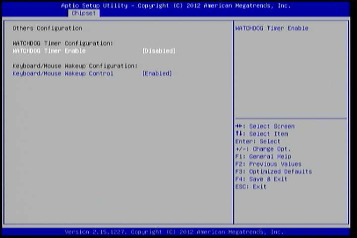
Figure 16: Illustration of Others Configuration screen
6.6.5.1. WATCHDOG Timer Enable
When this feature is enabled, an embedded timing device automatically prompts corrective action upon system malfunction detection.
6.6.5.2. Keyboard/Mouse Wakeup Control
When this feature is enabled, pressing any key of the keyboard or moving the mouse can wake up the system from suspend.
6.7. Boot Settings
The Boot Settings screen has a single link that goes to the Boot Configuration and Boot Option Priorities screens.
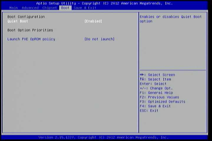
Figure 17: Illustration of Boot Settings screen
6.7.1. Boot Configuration
The Boot Settings Configuration screen has several features that can be run during the system boot sequence.
6.7.1.1. Quiet Boot
The Quiet Boot feature hides all of the Power-on Self Test (POST) messages during the boot sequence. Instead of the POST messages, the user will see an OEM logo. This feature has two options: enabled and disabled.
6.7.2. Boot Option Priorities
The Boot Option Priorities screen lists all bootable devices.
6.7.2.1. Launch PXE OpROM policy
Do not launch
Prevent the option for Legacy Network Device.
Legacy only
Allow the option for Legacy Network Device.
6.8. Save & Exit
The Save & Exit Configuration screen has the following features:
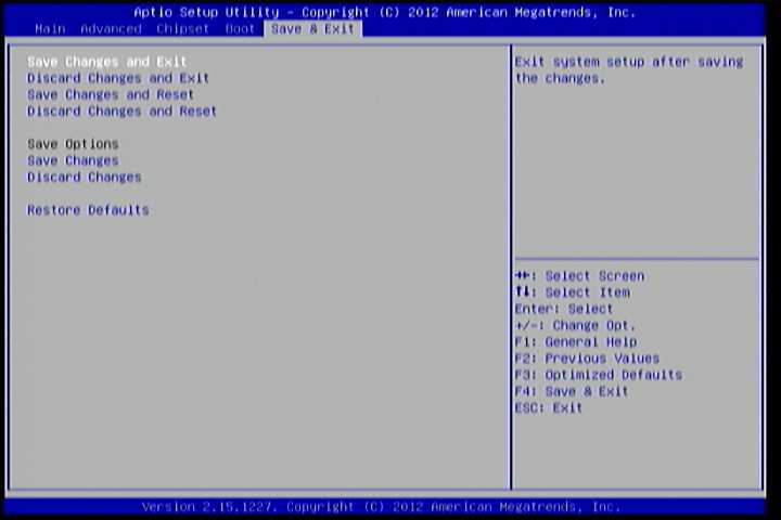
Figure 18: Illustration of Save & Exit screen
6.8.1. Save Changes and Exit
Save all changes to the BIOS and exit the BIOS Setup Utility. The “F10” hotkey can also be used to trigger this command.
6.8.2. Discard Changes and Exit
Exit the BIOS Setup Utility without saving any changes. The “Esc” hotkey can also be used to trigger this command.
6.8.3. Save Changes and Reset
Save all changes to the BIOS and reboot the system. The new system configuration parameters will take effect.
6.8.4. Discard Changes and Reset
This command reverts all changes to the settings that were in place when the BIOS Setup Utility was launched. The “F7” hotkey can also be used to trigger this command.
6.8.5. Save Options
Save Changes done so far to any of the setup options.
6.8.6. Save Changes
Save system configuration and continue. For some of the options it required to reset the system to take effect.